Background
Recently, we were called to resolve issues with a large RF cable distribution DAS system that was installed in a new hotel under construction by another company. (Another radio company besides Raycom was called to help with the system before we were contacted for assistance. They spent two weeks with several men working on the system and did not get it to work properly.) The system was highly complex due to the AHJ (Authority Having Jurisdiction) requiring a 3 band system with VHF, UHF T-band channel 14 and UHF T-Band channel 16. The VHF unit was manufactured by Fiplex and it was a class A two channel system with a very low +7dbm output power, complicating the distribution design and making the system operate at near 100% capacity, leaving little room for anything being done incorrectly. The UHF section was a high output +27dbm unit manufactured by Comba. Both units were combined into a single cable distribution system.
Each BDA unit was fed by a yagi antenna on the roof of the building utilizing a separate feed line to each antenna. The UHF antenna was pointed at El Mirador, the donor site for the ICS System which was at an azimuth of 336 degrees. The VHF antenna was pointed at Sequoia Park donor site at an azimuth of 204 degrees and the Bradshawe donor site at 177 degrees. Both antennas were located at the northwest corner of the building utilizing a non-penetrating mount held down by 8 concrete blocks.
The system had been installed and was inspected several times, failing inspection each time for performance issues of which there were many. The VHF system was suffering from coverage issues and degradation from many sources including lack of isolation between the donor and service antennas resulting in the need to reduce gain. The UHF section lacked coverage within the building, in spite of the fact that there were a large number of antennas on each floor.
System Overview and Explanation
Most people do not understand the concept of a DAS system. The concept is simple, but the implementation can be difficult. It requires a thorough understanding of RF principals and a rigorous adherence to quality with the installation.
Simply put, a DAS system picks up the radio signal outside the building from the source (which in this case are 3 different sources), boosts the signal and then distributes the signal throughout the building for use by radios from the AHJ. Also, it picks up signal within the building from radios from the AHJ inside the building and sends it off to the main system from the AHJ.

I like to use the analogy of a plumbing system to describe how the system works because most people understand the basics of plumbing. Each antenna in the DAS is like a shower head (or some people prefer to think of it as a sprinkler head in a lawn watering system) that sprays a fine mist of radio signals in all directions. The goal is to cover the entire building with the fine mist of radio signals, so regulating how much signal sprays out of each antenna, whether a directional head is used to spray into certain areas or an omni directional antenna is used to spray signal in all directions from the antenna, the location of each antenna to cover the area including high traffic areas such as elevator lobbies and determining how many antennas are needed to spray the radio mist everywhere. Although radio signals will penetrate walls, different materials offer a differing amount of resistance to the radio signal passing through the wall. Each and every physical object within the building offers some resistance to the radio signal, so having an understanding of how each obstruction affects the radio signal is essential to being able to predict the outcome of any design.
The antenna cable that connects all the antennas is like the pipes that bring the water to the shower heads. Signal taps determine how much signal is fed to each antenna by determining how much signal is siphoned from the main pipe to spray through the antenna. If the connectors are loose on the cable, it is like having water leak out of the pipes at the junctions. A spray of the radio signal out of the cable at a loose connection will cause a hot spot where the spray is concentrated. This robs the water pressure down the line so subsequent antennas down the line have low pressure, so the spray of radio signals will be below the strength that would otherwise be predicted. Besides leaking signal, poor connections inject signal loss into the cable distribution system which is equivalent to having an obstruction in the water pipe that kills your water pressure so that there is insufficient signal to spray out of the antennas down the line.
Problems Found in the System
Numerous problems were found with the system such as:
- Connectors that were improperly installed on the hardline cable in multiple instances. The copper shield was improperly flared causing the connector to be unable to grip the copper shield properly.
- Connectors were not tightened properly when attached to splitters, taps and antennas.
- Splitter values were not always the value shown on the riser diagram.
- Splitter values were not properly determined to create even signal distribution. Too much signal or not enough signal was siphoned from the main distribution cable causing improper distribution of signal.
- Connectors were cross threaded keeping some of the service antennas from receiving any signal whatsoever. . This caused cold spots in the coverage.
- The service antennas were mounted directly to concrete ceilings in the two basement levels. No information was available from the antenna manufacturer regarding the affect of the concrete to the antennas. Field tests were conducted by Raycom to determine the effect. We found approximately 3-6db degradation of the antenna performance which equates to (25%-50% efficiency of the antenna) when mounted directly on concrete.
- Additional antennas were needed to fill in signal in areas that were inadequately covered by the existing design while taking into consideration the signal levels available from the amplifier unit.
Summary of Work Performed
When we arrived at the project, it became necessary to review the system design and determine if the basic design was flawed or if the installation was defective. Since we had not been involved with the design or installation, we did not know what standards were used to implement the DAS system, therefore, we had to check everything. We started by measuring signal levels, investigating interference from nearby signals, checking for bad connections, testing antennas and testing the amplifier units. Here are some of the tasks that we performed:
- Moved the VHF antenna to the southwest corner of the building to eliminate the feedback path on the VHF system. The previous location at the northwest corner of the building pointed the directional antenna towards the service antennas inside the building. The new location pointed the antenna off the side of the building with the service antennas being on the back side of the directional antenna pointing at the donor site.
- Studied the system design to determine if it made sense, that there was sufficient signal in the different areas of the building.
- Traced cables to determine the cable routing throughout the building and if it matched the system design.
- Checked cable connectors to determine if connectors were installed properly. This often involved removing the connector to physically inspect the workmanship. Whenever a bad connection was found, we had to repair the connector installation or replace the connector entirely.
- Checked tap values to determine if the proper signal distribution values were employed.
- Tightened connections from the cable connectors to the signal taps and from the cable connector to the antennas.
- Remounted all antennas on B1 and B2 levels to space them 4” from the concrete ceiling to make the antenna perform properly.
- Tested return losses on cables to determine if we had bad connections or other issues that would adversely affect the performance of the system.
- Building was tested for signal levels with our spectrum analyzers and with calibrated portable radios.multiple times while working on the system to see the effect of the changes we had made to the DAS system.
Troubleshooting Philosophy
There was no single issue that made the system fail to perform properly. The process of troubleshooting is like peeling an onion. One can easily see the problems on the outer layer and until that layer is removed, it obscures the view of the problems at the next layer and below. After dealing with the problems of the outer layer, one can now move to the next layer. As each layer of problems were eliminated, it revealed the next layer of problems. As we proceeded through the layers of problems, eventually we were able to get to the core so that we could eliminate the last of the problems.
Specific Items Found

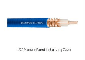
The single biggest problem we encountered was the quality of the connections. Approximately 75% of all the connections were loose, allowing signal to leak out of the cable. Some of the hardline connectors were professionally installed with good flaring of the copper to mate properly with the connector, but most of the connectors were poorly installed. Referencing Figure 1, one can see a professionally installed connector with proper flaring of the outer cable shield.
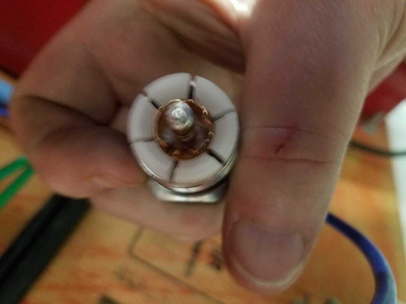
Compare that to Figure 2 with the copper shield looking like it is folded inward, causing the shield to be unable to seal against the flare in the connector body, the connector fails to grab the copper shield and the connector allows the signal to leak out of the cable. The connector will rotate on the cable when twisted instead of the connector grabbing the shield and holding rigidly to the cable.
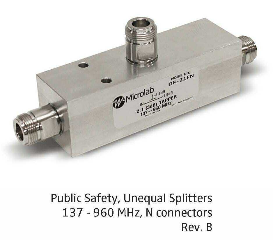
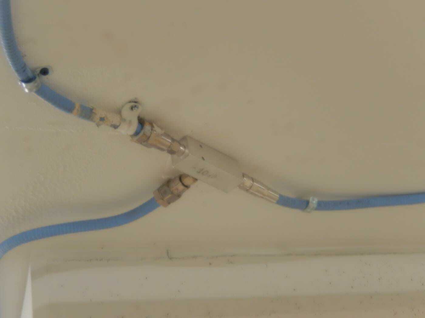
Each signal tap has 3 connections. The signal is fed into the input of the signal tap. If the cable connector is not properly secured to the signal tap, signal will leak out of the loose connection. The signal tap must siphon the correct amount of signal from the main line (input on the left and output on the right) to send to the antenna via the tap port which is the port that is in the middle facing up.
The tap value determines the amount of signal that is siphoned from the main line and sent to the tap connection. See Figure 3 to see a signal tap. The connection cable that is attached to the tap port must be properly secured to the tap and connected to the antenna. We found some of these cables cross threaded, so they did not make proper contact, so the cable did not properly connect the antenna to the signal tap.
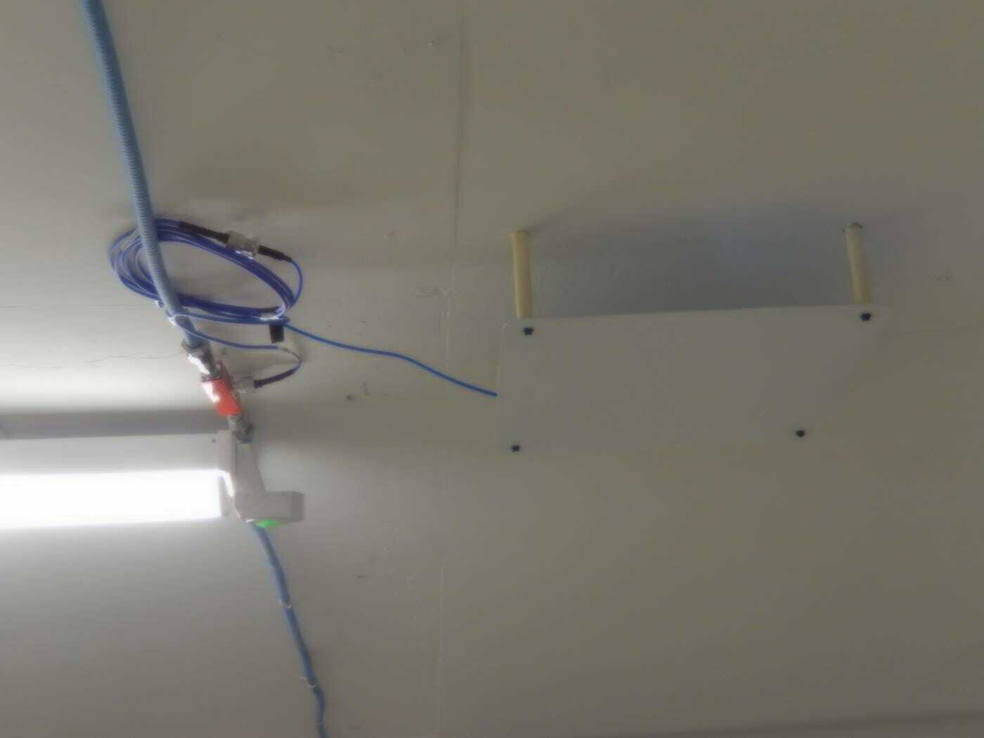
Every foot of cable has signal loss. Therefore, it is prudent to keep all cable runs as short as possible. Smaller diameter cables have more signal loss per foot, See Figure 4 of an antenna and signal tap with excessive jumper cable length coiled up next to the antenna. Excessive cable length wastes signal since there is signal loss in every foot of cable. Long small cables have even more signal loss, just like long small pipes kill water pressure.
Antennas in the basement levels were mounted directly to the concrete ceiling. Since this caused the antenna performance to degrade, we needed to figure out a way to space the antenna off the concrete. We created spacers from CPVC pipe by cutting the pipe into 4 inch lengths. We then mounted the antennas with 5 inch long Tapcon screws by drilling into the concrete ceiling and using the CPVC spacers to keep the antennas off the ceiling.

Many antennas were added on the B1 and B2 levels of the building to fill in areas that had insufficient signal. Some of these antennas were moved to provide a better line-of-sight view from the antenna to important area of the building such as the elevator lobby. Tap values were calculated to determine how much signal to feed to these antennas. When adding an antenna, we attempted to make the aesthetics of the antenna be pleasing per Figure 5 and Figure 6. Compare those figures to Figure 7 and Figure 8 which depict antennas and cables that were sloppy with the installation.
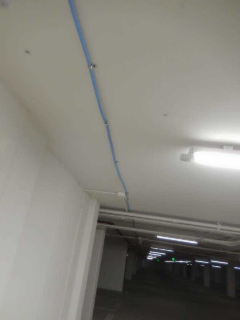
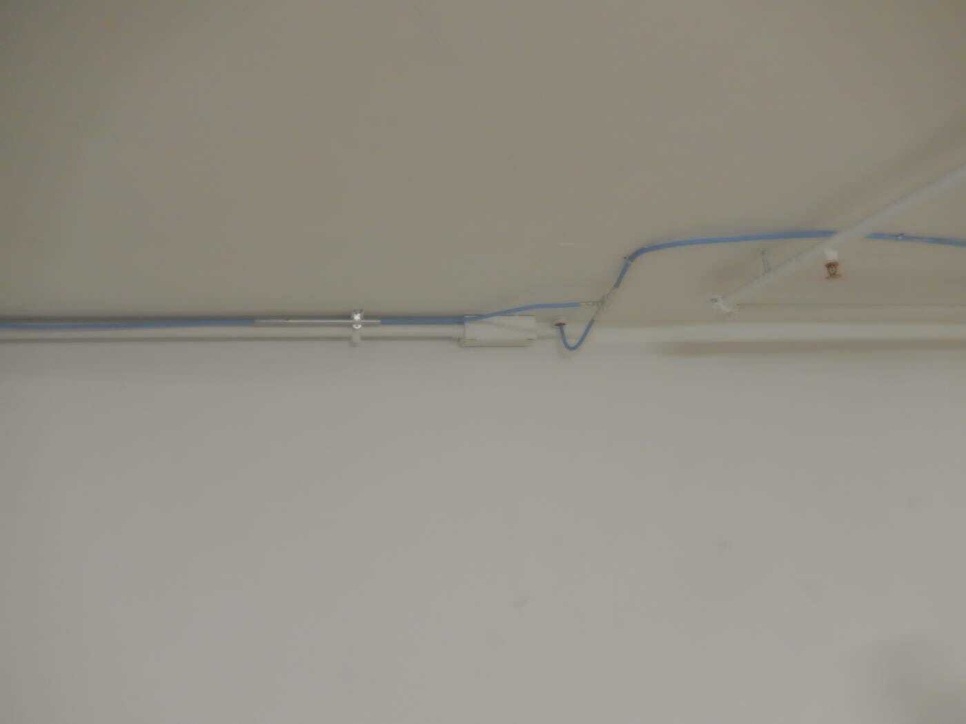
It appears that different portions of the job were installed by people with different ideas of what is considered to be an acceptable installation. In Figure 9, you can see a cable that is properly secured every 2 feet, the cable is pulled tight, has very few bends, is tight to the ceiling and looks professional. Compare that to the cable in Figure 7 which is sloppy, sagging, bent and looks like the installer was in a big hurry to finish and go home for the weekend to attend a big party.

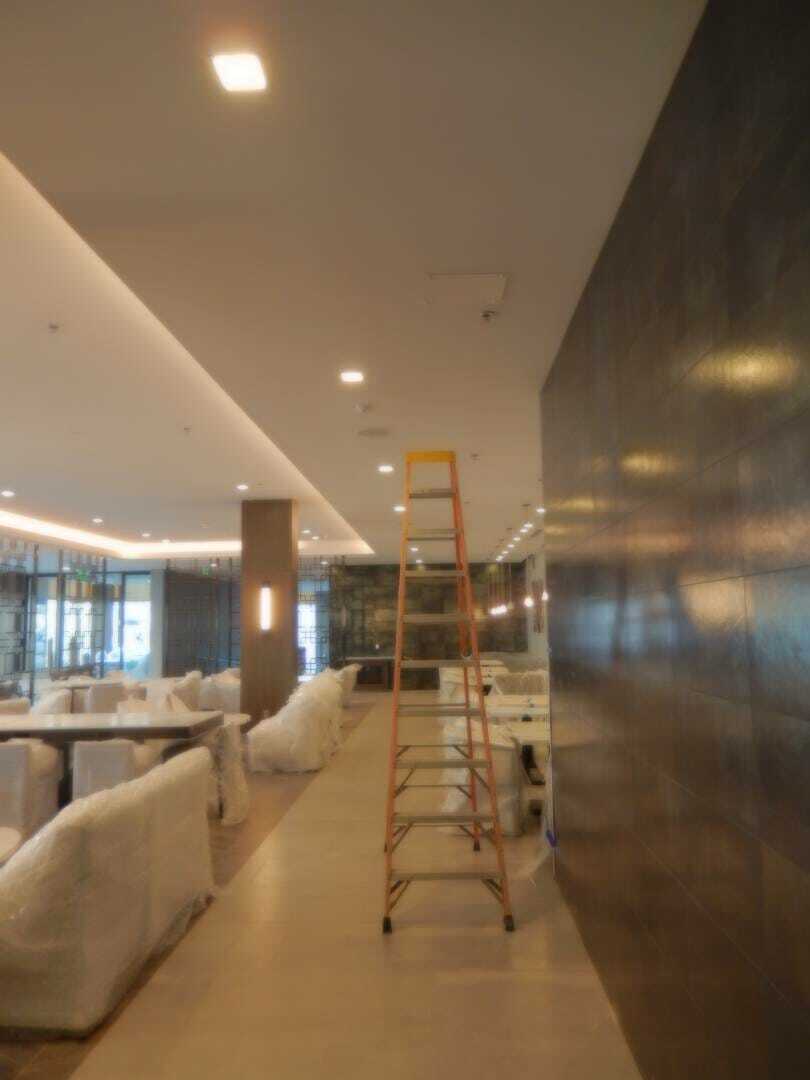
One of the antennas on the lobby level was installed on the restaurant ceiling near the north end of the building. See Figure 10. The antenna performed poorly because it was mounted on the drywall ceiling under a metal support above the drywall. Most antennas including this model antenna do not like being mounted near metal any better than being mounted to the concrete ceiling. If we moved the antenna, there would be a hole in the ceiling that would need to be patched and repainted.
We were able to reduce the collateral damage by leaving that antenna in place disconnected from the system and installing a new antenna above the drywall to radiate the signal.

Another area of the lounge had insufficient signal due to no antenna being in the area inside the restaurant / lounge. There was an antenna in the kitchen (Figure 11) on the other side of a significant wall that blocked the signal from radiating into the restaurant / lounge area. We installed another tap at the kitchen antenna and installed another antenna on the other side of the wall so that there was great signal in the restaurant / lounge. See Figure 12.
On level B1, several antennas were added or moved. In addition, we changed the values of the taps on the floor to redistribute the signal. The signal comes down from the first floor to B1 near the north end of the building and the signal travels south through the cable to the south end of the building. After we fixed numerous connections (See Figure 13 as an example of the one connector on the right that we had to replace because the existing connector was broken and the connector on the left was installed improperly causing the connector to be loose on the cable) along the line, there was great signal at the south end of the building, but the signal was weak at the north end which was the source of the signal. (This is reverse from the normal situation where you have strong signal at the source and weak signal at the end of the line which is a long distance from the source. This is due to the signal loss in every foot of cable that reduces the signal level at the far end of the cable and the fact that the signal taps siphon off signal to antennas along the line.) After investigating, it was determined that the tap values were incorrect as the taps were not siphoning off enough radio signal for the antennas at the north end of the building through the center of the building. We had to install new taps with the correct values to make the cable system perform correctly. We also added 2 additional antennas to fill in signal in areas that did not have sufficient signal from other antennas.
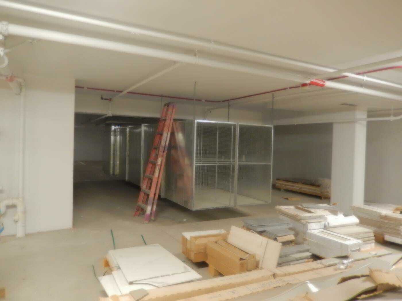
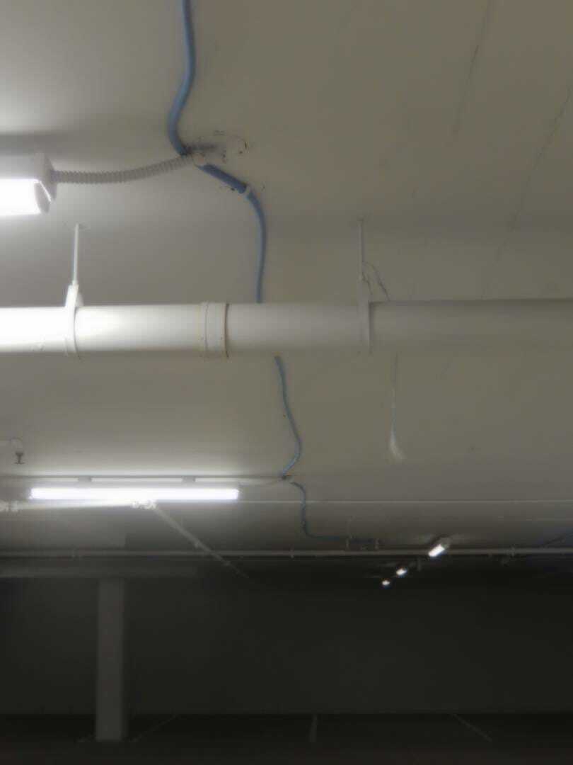
On level B2, several antennas were added or moved in a similar fashion to what we had done on level B1. At the north end of the building, we installed a new antenna to cover the area that was shielded by an air duct (Figure 14) that was used to remove vehicle exhaust from the level. The metal duct blocked the signal from the antenna nearby causing an area that was below the required signal level. We also installed another antenna where one had been previously located, but was removed by someone who worked on the system before we were called to help with correcting the system problems. Another antenna we added was on the south side of the south stairwell. The antenna on the north side of the stairwell was block by the concrete block that made up the stairwell to the south. We moved the antenna to the south side of the stairwell, but we then had a shadow on the north side of the stairwell. Finally, we added an antenna so that we were on both sides of the stairwell which eliminated the weak signal area.
The VHF BDA had several issues. Alarms were triggering under certain signal conditions which would cause the system to fail. Additionally, the output level of the BDA was below the rated value by at least 10db which was unacceptable. We had several conference calls with the factory engineers to get the BDA to perform properly and meet specifications. The calibration of the BDA did not match the levels that we saw with our test equipment, so the factory had to make adjustments with their proprietary software to calibrate the unit properly.
Summary
The process of investigating and repairing the DAS system involved several people, multiple trips to the property, ordering parts, waiting for delivery, perseverance, blood, sweat and a lot of hard work. It was necessary to keep digging to find the problems because most of the issues were hiding inside connections that were not necessary visible to the trained eye. Some of the bad connections were visible if you knew what you were looking to see, but many of the connections were located in places where it was difficult to access and the lighting was poor which made it difficult to investigate. This emphasizes the principle about the need to do the job right the first time, because it is too expensive to do it right the 2nd, 3rd or 4th time. We had almost 200 hours work to repair the system so that it would pass inspection. Additional work could still be done on the system to clean up the wiring that was not up to the quality of other portions of the system.