DAS / BDA / Signal Boosters / ERRS / ERRCS Systems
By: Mark Abrams
First, some definitions to alleviate some of the confusion over the terms. Many people have just found out that they need one of this systems which they have never heard of before to meet requirements for fire or police radio coverage inside a building.
DAS – Distributed Antenna System – This refers to the antennas installed in the building to fill in the weak signal areas
BDA – Bi Directional Amplifier – A radio frequency amplifier to boost signals in both the uplink and downlink directions. For full duplex radio repeaters the up and down frequencies are different, so the amplifier is filtered to up and down directions by frequency
ERRC – Emergency Responder Radio Coverage
ERRCS – Emergency Responder Communications System
ERRS – Emergency Responder Radio System
While the variations may be a bit confusion, these are all used to describe a system, or the components of a system to provide radio coverage inside a building where the structure or ground may be blocking the signal from the mountain top repeaters.
Distributed Antenna Systems aka DAS Systems, Bi-Directional Amplifier Systems aka BDA Systems or Signal Boosters are used for many radio applications including, but not limited to Fire Department, Police Department, Cellular telephone technology and two-way radio applications. The City of Los Angeles refers to these systems as an “Emergency Responder Radio System” or ERRS. The City of Long Beach refers to these systems as an “Emergency Responder Radio Communications System” or ERRCS. These systems extend the range of the radio signal into areas that would otherwise be considered a “dead zone” for the radio signals which are typically inside buildings (especially the lower floors of the building), elevators and basement areas of buildings. Dead zones can also be the backside of a building from where a transmitter is located because the building blocks the signal in that area or it can be an area behind a hill or mountain, in a valley or other area blocked by natural terrain. There are other methods of solving the problem of a lack of radio signal in a dead zone. They include different methods such as a passive repeater, satellite transmitters, satellite receivers, translators, transponders, simulcast sites, additional repeaters, etc. Each method has its advantages and disadvantages such as seamless operation and costs. Raycom / MRA provides DAS systems which are customized for each application. Since every building and environment is different, no two solutions are exactly the same. Raycom will analyze the area of the dead zone and design the most economical system solution for your application. Active DAS systems require extensive knowledge of radio propagation for designing and installing such systems. Aside from the legal requirements under the fire code, if the system is installed improperly, the system will cause significant radio interference in the surrounding area to other services which including cellular, PCS, police, fire, public works, WiFi, etc. The penalties for causing such interference can be severe, so having the job done cheaply by inexperienced personnel usually proves to be penny wise and dollar foolish.  Under the 2013 and 2016 California Fire Code, all new buildings (or major remodels) that block the radio signal from the fire department radio system are required to “fix” the problem. This is done by installing some type of signal enhancement system which can pick up the signal outside the building and pipe the signal to the building interior. The following are the two basic types of systems:
- Passive Repeater System – Passive repeater systems will work in very limited circumstances where the dead zone is limited to a few thousand square feet and there is a very strong signal from the fire department outside the building. The system consists of a donor antenna on the roof of the building, coax cable, 1-3 signal splitters and the appropriate number of service antennas inside the building. There are no active components to power or fail. They are relatively inexpensive to build and install compared to the active DAS systems, but will work only in very limited circumstances. The signal from the fire department must be -50dbm or better, the dead zone must be an open space (typically a garage area) without significant blockage from walls and you must be able to have the inside antenna within about 30-40 feet of all of the dead areas. Circumstances will be right for these systems less than 3% of the time.
- Active DAS System -. This system uses an active amplifier system to pick up, amplify and rebroadcast the radio signal from the fire department, police department, cellular, PCS or whatever signal you are trying to bring into the building. The systems do not modify the signal, they only boost the signal to be stronger so that it can be distributed throughout the building. If the system is for the fire department, there are many requirements that vary by jurisdiction which typically include 24 hour battery backup, the need for the equipment to be located in a 2 hour fire rated room and having the vertical riser cables located in a 2 hour fire rated riser which is not always available in the building design. The active DAS systems are used in 97%-99% of all the situations.
NEWS FLASH!
Raycom announces the availability of a 2 hour fire rated cable, connectors and mounting clamps for immediate delivery to solve your DAS requirements without having to build a special 2 hour rated soffit or riser for your DAS system. There are now two different manufacturers of 2-hour fire rated cable available.
Active DAS systems are divided into two basic classes of operation.
- Class A – These signal boosters are known as channelized units. The amplifier will break down the radio signals into individual radio channels, amplify the individual signals, recombine the signals to a single antenna and rebroadcast the signals into the building or dead zone. This class of signal boosters has the advantage of being able to single out individual signals to rebroadcast while not rebroadcasting other signals. This is especially important whenever there are radio signals from entities that do not want their signal to be rebroadcast. Under the FCC rules, you must have permission to rebroadcast radio signals, so using the Class A amplifier system will eliminate any need to determine if any foreign signals need permission. Also, since you are only rebroadcasting the desired signals, all the energy in the rebroadcast is for desired signals and none of it is for undesired signals. There is only so much power available in these systems, so conserving the energy for the needed signals is sometimes required to make the system work. The disadvantage is that you need to add additional hardware any time the entity (such as the fire department) decides to add another frequency to their system. These systems are the less common amplifier units being installed.
- Class B – These signal boosters are known as broadband units. The filters in the unit pass a certain range of frequencies while eliminating frequencies outside of the filter range. The system filters pass a range of frequencies to the amplifier, boost the signal and rebroadcast the signals into the building or dead zone. The problem with Class B boosters is that any radio signal within the passband of the filters will be rebroadcast, regardless of whether you have received permission to rebroadcast their signals. The advantage is that if the fire department (or any other entity whose signal you are rebroadcasting) decides to add another radio channel, you do not have to add any hardware to rebroadcast that channel provided it is within the existing frequency range of signal booster. These are the more common amplifier units being installed.
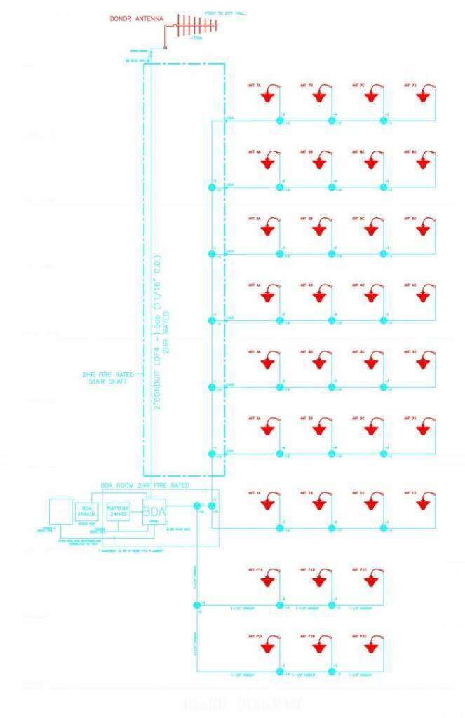
Typical DAS Riser diagram
Riser Diagram – The typical riser diagram shown here depicts a typical installation of a 7-story building with 2 underground levels. The underground parking levels utilize 3 antennas on each level due to the parking areas having an open type of construction thus allowing the radio signal to propagate easily throughout the parking levels. The tenant floors of the building have many more walls which requires 4 antennas per floor to reliably radiate the signal throughout the floors. (Since many buildings vary their square footage by floor, it is not uncommon to have different numbers of antennas on different floors which also means that it may be required to vary the amount of signal that reaches a particular floor.) Signal splitter are available in multiple values from 1% of the signal being tapped from the main cable to feed signal to a particular area to 50% if the signal which allow the designer of the system to take different amounts of signal to be sent in the different directions to different areas of the building. These values are typically chosen to evenly distribute the radio signal throughout the floors, considering the signal loss of the cable, connector loss and signal splitter loss. However, there are times that one may want an uneven distribution due to certain areas of the building having acceptable coverage without any assistance and saving more of the signal to provide coverage in areas of the building that does not have sufficient signal. There are hundreds of considerations made to properly design a DAS system for any given dead zone where the signal falls below the requirements of the local AHJ (authority having jurisdiction).
In the City of Los Angeles, both the equipment and the riser cables must be protected by being installed within a 2-hour fire rated area. Cables that are horizontal turn then vertical must be considered vertical riser cables. Once the cables turn horizontal for the last time, there is no longer the need to keep the cables within a 2-hour enclosure, thus making the cable runs to the service antennas on each floor significantly easier (and less expensive) to run and install. The theory behind the requirement is that the fire authority does not want a fire to take down the entire system or major portions of the system, but the loss of an individual antenna that covers a portion of a floor is an acceptable risk.
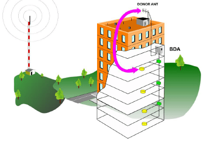 Referencing the figure of the building to the left, the signal from the nearby tower illuminates part of the building with sufficient signal so that antennas are not required throughout the entire building. The building depicts a 7 story building with 2 underground levels, similar to the riser diagram above. Both of the levels below ground have antennas to enhance the radio signal. The ground floor does not show an antenna because that floor is glass all the way around the building (of a variety that does not adversely affect radio reception) which allows the signal to get inside the building well enough that nothing is required to bring up the signal level. (Most glass these days does adversely affect radio reception.) The 2nd and 4th floor both have antennas to bring up the signal and the 3rd floor gets enough signal level from the 2nd and 4th floors to work with the particulars of this installation and the type of construction of the floors that allows the service antenna signal to penetrate the 3rd floor. The 5th – 7th floors do not have any antennas because there is sufficient signal without any enhancement. Also, there is more signal on the side of the building facing the radio transmitter and less on the side of the building opposite the radio transmitter. The reason that the antennas are shown close to the opposite side of the building from the radio transmitter is to place more signal in the weak area and less signal on the side of the building facing the transmitter that works without any signal enhancement.
There are two basic technologies employed for the different classes of DAS systems for distributing the signals around the building. These are the RF (radio frequency) distribution which uses RF cables throughout the building and the fiber system that uses a combination of fiber and RF cables to reduce signal loss and to increase the size of the area that can be covered with a single DAS system. The different technologies are as described below:
- RF Distribution – These systems utilize RF cables throughout the building for all cabling. There is typically a limit on the number of square feet that can be covered with a system using exclusively RF distribution which is about 500,000 square feet. Systems that are larger typically utilize fiber distribution. The cable has signal loss in every foot of cable, so the more cable that is run, the more signal that is lost. The amplifiers that are available have a limit of typically 2 watt output, but that power is divided amongst all of the radio signals that pass through the amplifier system in the ratio of their relative input levels, so you can easily run out of signal for the building when you take into account the limits of the amplifier and the signal loss in the cables and the signal splitters that feed the various antennas.
- Fiber Distribution – Fiber systems are used on larger projects for several reasons. They include the lack of signal loss in the fiber cable, the cost of installation and the fact that RF distribution is limited in the number of square feet that it can cover. Fiber systems use fiber from the head end (main unit) to all the remote units. Each remote unit will amplify the fiber signal and turn it back into RF at typically a one-watt level. That output is now used to distribute signal on a single large floor or multiple smaller floors to cover up to 200,000 square feet with RF cable distribution. Each floor (or group of floors) will have a separate remote unit with the one-watt output and typically as many remote units as needed can be added to the system. If you have 50 floors in the building, you could have one remote unit per floor for a total of 50 remote units with one watt each or effectively 50 watts of power for the entire building which cannot be done with RF distribution systems. Also, a campus that has multiple buildings can be fed with a single head end with a fiber feed to each building, thus making the system far more economical for such situations.
Fiber Cable Types – There are two basic types of fiber cable. There is multimode cable and there is single mode cable. Multimode cable can carry more information on it because it has several modes of operation that can be utilized simultaneously. However, it has a distance limitation of about 1500 feet due to the high signal loss through the cable. Single mode cable can carry less information, but has very little signal loss, so it can be run for up to 10 miles without having to install a fiber repeater system to boost the distance that the signal can travel. All the signal boosters that we have installed have utilized single mode cable. We are unaware of multimode fiber DAS systems as of the time if publication of this section.
RF Cable Types – There are hundreds of different types of RF cables which are available, but only a few are appropriate for the job of installing signal boosters. Most jurisdictions require either fire retardant cables or plenum rated cables. (The fire rating refers to the material that is used to make the cable jacket which determines how susceptible the cable is to catch on fire and be damaged.) Often a cable will be partially in an area requiring fire retardant cable and then pass through an area that requires plenum rated cable. The cost of splicing the cable plus the reliability factor and the need to be able to access the junction between the two cables makes it in infeasible to splice the cable, so it is normal to run all plenum rated cable. In a typical installation, a standard cable is run from the rooftop donor antenna (which picks up the signal from the fire department or other radio signal source) to the BDA amplifier system because the cable extends outside the building on the roof to connect to the donor antenna that picks up the signal from the fire department or other radio signal source. The plenum rated cables are not ultraviolet (UV) rated and will deteriorate considerably over time, thus causing a long-term maintenance issue. All other cables in the system are typically plenum rated cables so that the building inspector does not make us replace fire retardant cables with plenum cables whenever the inspector decides we have placed a fire-retardant cable in an area that requires plenum cable. This often happens in new construction and the cost of changing the cable far exceeds the cost differential savings between the two cables. All RF cables are coaxial cables. However, in the video and cable TV industries, all coaxial cables are 75-ohm cables. In two-way radio systems, all coaxial cables are 50-ohm cables. We have seen many installations done with 75-ohm cable that should have had 50-ohm cables. These systems exhibit problems that are difficult to trace and expensive to repair. Be certain that you use the correct cable for the job.
Flexible Braided Cables – These cables have higher signal loss per foot and are typically used for short jumper cables. The braided shield on the cable has more signal leakage through the cable which can adversely affect the performance of the system, but has minimal effect with jumpers due to the short length of jumper cable. Also, there are many types of braided cable where the braid is over an aluminum shield. These cables should be avoided due to the potential to cause intermodulation products which is a type of radio interference for which the building owner can be held liable. There are some limited specific circumstances where it may be appropriate to use this type of cable, but it is best to avoid this cable unless there is no practical way to avoid using it. The only flexible jumpers that we use are high quality double shielded, silver plated, plenum rated cables.
Semi-Rigid Hardline Cables – Most RF distribution is done with hardline cables due to their lower signal loss per foot of cable and the shielding in the cable which is extremely important to prevent feedback in the system (which is described below). The most common cable is the ½” diameter hardline cable which is used for 98% of all of our cable runs. When a cable needs to be run a long distance without a number of taps or splices such as between buildings, then we use a larger cable that is 7/8” diameter to reduce signal loss. This cable is much heavier, harder to bend and far more expensive. Also, the cable connectors for the 7/8” cable are very high priced. Therefore, we only use the 7/8” cable in very limited circumstances.
There are hundreds of different hardline cables from different manufacturers, each being appropriate under a specific set of parameters. The proper choice of hardline cable for a specific installation is essential for the project to be completed, turned up and have its operation certified.
The Delicate Balance of DAS Systems
DAS systems all operate in a mode where the transmit frequency is the same as the receive frequency. This places a stringent requirement on the system designer and installer to be certain that the system does not feed back into itself, thus causing radio interference. When the RF feedback occurs, a small portion of the output of the amplifier gets back into the input of the amplifier, thus causing the feedback loop. You will not hear anything that is audible because it is a radio signal that is feeding back, but it will cause severe radio interference to anyone on a nearby frequency and it can destroy the amplifier unit in your system. The feedback loop is prevented by proper placement of the donor antenna on the roof of the building in relation to the physical location of the service antennas inside the building. If you perform a remodel in the building, it is necessary to have the system reviewed by an expert such as MRA DBA Raycom to be certain that you did not unbalance the system with cut or shorted cables or that you did not create a feedback path that will result in the system feeding back through excessive coupling of the signal from the donor antenna to the service antennas. This is similar a singer on stage standing in front of the PA speakers and getting the feedback screech when they get too close to the speakers. This is caused by the sound from the speakers being picked up by the microphone, being amplified and being sent out the speaker even louder again which is then picked up by the microphone again. The process continues with the screech until you break the cycle by moving away from the speakers or covering up the microphone to prevent the speaker sound from getting into the microphone.
In the adjacent drawing, the feedback path is showing between the antenna on the roof and one of the antennas inside the building. This is caused by the signal on the roof reaching the antenna on the 4th floor (and vice versa) of the building. The signal is shown at the roof of the building, bending around the outside of the building and re-entering the building on the 4th floor which is now picked up by the 4th floor antenna. In reality, the signal will penetrate the roof of the building and the floors until it reaches the 4th floor antenna most of the time. However, there are times when the signal will follow the path shown by the arrows by reflecting off the side of an adjacent building or other nearby object.
The DAS Project Process
We are here to deliver a quality product at an affordable price. With our extensive experience, we can install the most reliable system with superior performance much quicker than more economical than any other company. We use innovative solutions to figure the lowest cost method of providing you with the needed radio coverage to save you on the unexpected surprise cost of installing a DAS system.
Any project is easier to do when there is sufficient time to plan and implement the system. We routinely are called by building owners, developers, general contractors, sub-contractors, managers, architects, engineers and other interested parties when the building is ripe for issuance of the Certificate of Occupancy, but they get a surprise last minute correction notice from the inspector that they have not completed the DAS requirements. We then get emergency calls to install a system on short notice. Since we keep all the materials in stock for most common DAS systems, we are able to move quickly to take the heat out of your problem. The following is a discussion of what we need from you to solve your problem:
- Price Quote – Every job is custom because no two buildings are the same. Even with identical twin buildings, they are in different locations and they will not have identical dead zones for the fire department radio system within the building. To provide you with a price quote, we must design the system unless you are providing us with a DAS design to be built and that rarely happens. This requires architectural floor plans of each floor and the roof of your building to determine its size, shape, dimensions and construction materials in order to estimate the dead zones and determine what it will take to bring the signal into the building.
- Jurisdiction – Since each AHJ has different requirements, we must know which jurisdiction has control over the development of your project. After obtaining the architectural plans for the building, we design the project to comply with the regulations of the AHJ in mind. Only then can we provide a reasonably accurate price quote.
- Job Walks – Often a site walk is very helpful in determining issues that are not apparent from looking at the plans if the building. If the building is in construction, we can get a better idea of the specifics of the building and how the surrounding buildings affect the radio signal in your building. We can often determine that some of the floors will not require DAS antennas or we can find an easier way to perform the same installation. These items will affect the price for the DAS installation, often in your favor because without the information of the job walk, we have to make assumptions that may not be valid and increase the price quote.
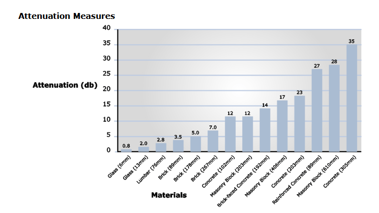
- Determining Coverage from Plans – Coverage estimates are just that, an estimate. There are computer programs that can help to give you a prediction of the coverage within a building. One such program is written by IB Wave which is the most accepted program in the industry. The program is very expensive (in the $50K price range) and is necessary for designing “neutral hosts” (a DAS system for cellular phones that handles multiple service providers) for large buildings such as office buildings, apartments, condos, sports stadiums, etc. With DAS systems for the Public Safety Fire Department radio systems, the program is not needed until a very large building is being fitted with a DAS system. The signal strength outside the building can be estimated from radio propagation software that is readily available for the industry (in the $5K-10K price range). The software does not take into account local obstructions such as trees or the building next door in the path of the radio signal from its source nor will not predict the coverage inside the building which is the signal level that is regulated by the state fire code. The actual signal level outside the building can be measured with the proper equipment which requires a trip to the property. Predicting coverage inside a building requires the IB Wave software or some experience with
 typical signal loss values for different construction materials that are used in different buildings. (The chart depicted above shows the typical radio signal loss from different materials.) In order to design the system which must be done to estimate the system cost, one must take into account the signal strength as it passes through different materials in the structure. A good approximation of the signal strength inside the building (which will change a small amount as the construction is completed) can be taken inside the building once the building “skin” is in place which included the stucco, siding and windows. A more accurate measurement can be taken once the drywall is on the walls and all of the doors are in place. The design of the DAS system must provide the minimum signal level required by law throughout the building while considering changes with distance from the DAS antennas, frequency of operation, construction materials, number of walls, cable loss, signal path loss and many other factors that affect the ultimate performance of the installed system.
 - Fire Department Plan Check – To get your plans approved by the AHJ, we must submit plans for approval. Plans are drawn using CAD files, so we must have access to the CAD files drawn by your architect. We can use PDF files for the initial evaluation and design. However, we cannot use the PDF files to get plan approval if we are awarded the project. It takes us typically 1-2 weeks to draw the plans and input those plans on the existing CAD files. We typically have several rounds of corrections between our designer and the CAD draftsman to make our corrections prior to submittal to the AHJ for plan check. Some jurisdictions offer plan check that are over the counter while others require 6 weeks for routine check. The majority of the construction projects are in the City of Los Angeles which requires 6 weeks for plan check.
- The Optimal Time for Cable Installation – The best time to install the antenna cables is after the framing is finished, the skin of the building is complete with windows, the drywall is up on the walls, the drywall is on the ceiling joists (if there is a drop ceiling) or the drywall is not on the ceiling (if there is not a drop ceiling). Since some of the cables are pulled through conduits, the conduit installation should also be completed before the cables are pulled through the conduit.
- Conduit Installation – Your electrical contractor or low voltage contractor can run the conduit for the DAS system. They must pull the electrical permit for the DAS system. The conduits must be installed according to our design instructions to meet the code requirements for conduit size and locations. The electrical permit must be signed off prior to the inspection with the fire inspector.
- DAS Installation – Every project is different, but all require conduit work. California code requires a 2” riser conduit from the DAS equipment (which is typically located in a mechanical room or the MPOE located in the lower levels of the building) to the donor antenna on the roof of the building. Some jurisdictions require 2 hour rating for the conduit and some require 2 hour rating for all vertical risers on the distribution inside the building. Our installers will route all cables, make all connections, attach all the antennas (which typically look like a Frisbee or a smoke detector on the ceiling) and test the entire system with our sophisticated test equipment to verify the integrity of the antenna system.
- Extended Construction Schedules – In buildings where there is a large amount of time between our cable installation and completion of the system, there is a tendency for other trades who are unfamiliar with delicate RF cables to cause damage to our cables. We make every reasonable effort to prevent this situation, but it is not always possible to prevent all damage. There are times when we have to run cables through ceilings before they are closed up with drywall, but the conduits for the vertical risers are not completed. This causes difficulty in protecting the cables from damage, so having a plan that works for all trades will reduce everyone’s costs.
- Equipment Installation – We can install the main equipment for the DAS system any time the equipment room is ready. Painting in the room is easier to accomplish if it is completed before our equipment is installed. The main amplifier equipment and battery system are the two most expensive components of the system and they are easily removed by unauthorized personnel, so we do not like to install the equipment until there is a locked room for the equipment. All systems require a dedicated 20A circuit (it cannot be a shared circuit by code) to power our equipment. We are also required to ground the equipment, so the electrical contractor needs to provide an electrical ground. The 5 alarms that are required by code must be wired to the DAS annunciator that is located in the building lobby using two CAT5 cables. The annunciator provides the alarm signals to the fire alarm company who monitors the alarms per the fire code. (See next main heading “Fire Department DAS System Requirements”)
- Turn Up and Testing – Raycom will program the amplifier (BDA), adjust the amplifier for proper operation and test it once the system is complete. Each antenna system (both the donor antenna on the roof and the distribution antennas inside the building) must be tested to determine the circuit integrity and performance. We then check signal performance in all areas of the building. (If an internet connection is provided, we can remotely program, test and monitor the system.) Once we determine that the system is fully functional and is providing the proper coverage and we have the alarms tested, we can schedule inspection.
- Inspection – After everything has been fully tested, Raycom will schedule the inspector to inspect the performance of the fire department system. We will escort the inspector around the building for the inspection and assist the inspector in conducting their tests. If any issue surfaces during the inspection, we will attempt to rectify the problem while the inspector completes their inspection so that the inspector does not have to return for another inspection.
Example of an Installation That Went Very Wrong
When you have inexperienced people working on a system, things can go very wrong! Recently, we were called to resolve issues with a large RF cable distribution DAS system that was installed in a new hotel under construction by another company. The system was highly complex due to the AHJ (Authority Having Jurisdiction) requiring a 3 band system with VHF, UHF T-band channel 14 and UHF T-Band channel 16. The VHF unit was manufactured by Fiplex and it was a class A two channel system with a very low +7dbm output power, complicating the distribution design and making the system operate at near 100% capacity, leaving little room for anything being done incorrectly. The UHF section was a high output +27dbm unit manufactured by Comba. Read the case study
Example of a Difficult Raycom Installation
Every contractor has jobs that they remember and from which they learn valuable and often costly lessons. Raycom is no different as we have had jobs that have gone smoothly and we have had jobs that turned out to be difficult. The difficult jobs always seem to provide the best stories of how one can overcome adversity and still succeed. The story we tell is one that is within the past two years and has made us a better DAS system provider as a result of the difficulties that we experienced in the job that we describe here. Story of a difficult installation
A More Difficult DAS Installation
It seems that Raycom has learned another set of lessons from another DAS job. Read the story in excrutiating detail about how the customer’s untold requirements caused us to double our labor and how the equipment manufacturer put the squeeze on us.A More Difficult DAS Installation
The Rush Job
We were contacted by a customer to install a DAS system into a building that was essentially complete and almost ready to obtain the Certificate of Occupancy. At the “final” inspection, the customer was informed by the fire department that their building lacked radio coverage from the Riverside Public Safety Radio Systems. Read The Rush Job Read DAS Systems Testimonial Letter
Another Rush Job
We were asked to quote an installation of a new BDA in an existing DAS system due to the BDA failure. At Raycom, we felt that we could repair the existing system instead of replacing it like all the other vendors had said that it needed to be done. We saved the building over $25K by repairing the system instead of replacing the system. Read Another Rush Job Read Another DAS System Testimonial Letter
Fire Department DAS System Requirements
The State of California enacted a requirement for fire DAS systems in 2013. They updated the requirements in the 2016 fire code. Each local jurisdiction is required by law to enforce the California regulations as written, but they are fee to embellish the regulations with their own set of regulations for DAS systems. Many jurisdictions have adopted the California Regulations as written by California and many have embellished the California Regulations with their own additional requirements, thus making the installation of DAS systems within their jurisdiction even more difficult and expensive. The California Regulations call for several requirements which are:
-
- NEMA4 rating on the amplifier equipment
- Fire engine color red on the main equipment
- Five alarm outputs to be monitored 24 hours / 7 days
- Amplifier Failure
- AC Power Failure
- Donor Antenna Failure
- Low Battery
- Battery Charger Failure
- 24-hour battery backup
- Testing requirement require each floor to be broken up into 20 roughly equal areas which must have a received signal strength of -95dbm or greater. Passing grade requires that no more than 2 non-adjacent areas fail on each floor of the building. If the building fails, then you must install the DAS system to bring up the coverage to acceptable levels.
The above are the basic requirements. There are other requirements which can be determined by reading the following links:
Section 510 of the California Fire Code.
Full text of the 2016 California Fire Code Title 24 Part 9
Annual Maintenance Requirements
The California Fire Code requires that DAS systems be annually tested and certified like many other systems within the building. The specific requirements vary by the AHJ. Raycom can perform the annual testing of your system to verify the operational parameters of your system. We offer an annual maintenance program which includes the cost of the annual verification required by the fire code. We will perform the following:
Verify that you are still getting the proper coverage from your DAS system. We have to walk the building taking signal measurements to verify operation.
- Verify that you are still getting the proper coverage from your DAS system. We must walk the building taking signal measurements to verify operation.
- Verify the alarms required that are handed off to the alarm company. We must verify that the alarm monitoring is fully functional.
- Verify the battery system is functional. We test the battery system and extrapolate its capacity. Batteries must be periodically replaced.
- Measure the system gain and amplifier performance. Compare the system performance to the recorded measurements to determine if there have been changes in system performance.
- Test the cable and antenna performance. Inspect your cables and antennas to verify the integrity of the connections. Sweep the antenna system to verify return losses.
- Check the donor antenna for wear & tear, physical damage and verify that it is mounted and aimed correctly. Many jurisdictions reconfigure their systems from time to time and the building owner is required by law to make any changes necessary to accommodate the changes by the AHJ.
- Nearby construction of new buildings or remodels can block the radio signal into certain portions of your building. If that portion of your building relied on the natural signal and not the DAS system to provide signal, you will have to extend your DAS system. You are required to make changes to your DAS system to fix any signal deficiencies, regardless of the cause. The cause may not be your fault, but it is still your responsibility to resolve according to the fore code.
Jurisdictional Differences for Fire Department DAS Systems
Many jurisdictions have enacted additional requirements for the DAS systems. The most notable one is the City of Los Angeles which has enacted an eight page document outlining their requirements. The City of Long Beach has also enacted additional requirements in their ten page document that are even more stringent than the City of Los Angeles. Many other cities have enacted their own additional regulations which makes it more difficult to install, maintain and certify the equipment and installation. Copies of various city requirements are attached for reference with the following links:
DSA Announces Fire Code Requirement Enforcement Effective January 2021
Cities
LA City Fire Codes Ver II Aug 7, 2018
Long Beach Emergency Responder Radio Coverage Regulation Sept 6, 2017
Glendale Emergency Responder Communications System Jan 9, 2015
Beverly Hills FD emergency Responder Radio Coverage 2020
Brea Fire Emergency Responder Radio Coverage Guideline
Newport Beach Emergency Responder Radio Coverage System
Huntington Beach ERRS Requirements
Irvine 800mHz testing and acceptance
Irvine 800mHz testing certification
San Francisco DAS Requirements
San Mateo ERRS Requirements 2015
Santa Rosa ERRS Inspection Checklist
Stanford Palo Alto ERRS Requirements
El Segundo Emergency Responder Radio Coverage
Arcadia Emergency Responder Radio Communications
Corona CA Final Emergency Responder Radio
Santa Clara SDS C 2 Emergency Responder Radio Coverage systems
Sunnyville ERRCS Code and Policy Requirements
Berkley FD Emergency Responder Radio Coverage System
Mountain View CA ERRS Submittal Requirements 6-23-15
Burlinggame Emergency Responder Radio Coverage Guidelines
Hillsborough Emergency Responder Radio Coverage Guidelines
Counties
Los Angeles County Fire Code Requirements
Los Angeles County Fire Department Overview
Los Angeles County Contract Cities
OCFA Emergency Responder Digital Radio
Clark County Permit Procedures for ERRCS
Clark County Mandates Safer Buildings