In the radio business, we tend to use certain terms on a regular basis, otherwise known as the industry jargon. In order to understand our talking points or items contained herein on the website, we have provided this glossary of terms to assist you to understand what is being said.
GENERAL INFORMATION
Radio — A device for the reception or transmission of voice, data, or other information by wireless means. A Radio Frequency (RF) signal carrier is modulated by some means and transmitted. The receiver selects same frequency and demodulates the information back to it’s original form. Two-way radios, cell phones, broadcast stations and Wi-Fi access nodes are all examples of radio.
1G, 2G, 3G, 4G, 5G – Refers to the “generation” of equipment that is being used by the cellular provider. The higher generation is more sophisticated and will provide a faster data connection. The tendency is to consider the generation indicative of the frequency that is being used by the smart phone, but the frequency is independent of the service level being offered. 5G can be implemented in any frequency band used by the cellular carriers, just as 4G or 3G. Each cellular carrier decided which technology to implement on which frequency.
PTT – Push-To-Talk which is typical of most mobile radio systems. When you press the PTT button, the radio ceases listening and begins transmitting a signal. To listen, one must release the PTT button.
Conventional – A radio system that operates in a conventional mode which has a radio user typically use one radio channel or frequency. Since most radio channels are shared, it operates like an old party line phone or a current home phone with multiple extensions. (Only one phone call can be made at a time and anyone else in the house must wait for the other person using the phone to make a call.) When the channel is in use, one must wait for the channel to clear before making a radio transmission to avoid interfering with the co-channel user.
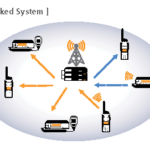
Trunked – A radio system that utilizes more than one repeater at a specific location and has some automated system that assigns users to different channels so that the user does not typically have to wait for a clear channel unless all the channels are occupied simultaneously. Trunked radio systems provide a higher user satisfaction level than conventional radio systems on shared channels because the user has the illusion of privacy (a virtual private channel) and having a channel to themselves. It is similar to having a VPN in the computer world.
RADIO SERVICES
CB Radio – Known as “CB” or Citizens Band radio, it us used for personal and business use by the general public. There are several Citizens Bands that are used for different purposes. The traditional CB radio operates in the 27MHz band of frequencies utilizing AM (Amplitude Modulations) or SSB (Single Side Band) modulated transmissions which is used by long haul truckers to communicate with each other, weigh stations and terminals. With 40 channels from which to choose, one generally cannot find a clear channel at busy times of the day. The 27MHz frequency will sometimes travel hundreds or thousands of miles depending upon atmospheric conditions which are primarily determined by the ionization of the ionosphere which is heavily affected by the sunspot cycle. The CB radio was featured in the movie Smokie and the Bandit where the radio was used to help avoid the state police and highway patrol aka Smokies in the movie. CB radio is primarily for personal use, but the business use of the radio is not prohibited.
GMRS – General Mobile Radio Service which is another form of radio for personal use. The GMRS channels operate on 25KHz wideband channels in the 462 MHz and 467 MHz range using FM (Frequency Modulation) modulation. Repeaters are allowed in the band and can be used to extend the range of the GMRS signal significantly. Both licensed and unlicensed operation is allowed, however, the licensed operation allows for higher power radios which get better range. Due to the proliferation of FRS radios, interference is likely because the FRS channels overlap with the GMRS channels.

FRS – Family Radio Service which is an unlicensed Radio Service in the 462MHz band. The FRS channels are half-way in-between the GMRS channels, operate on 12.5KHz narrowband channels and are used strictly used in simplex mode direct radio to radio without the help of a repeater. FRS radios are limited to a low power of 500mw on 7 of the channels with an integral antenna so that the user cannot use a higher gain antenna to extend the range of the radio. The power is limited to 2W on the other 7 channels with an integrated antenna. FRS radios will receive interference from nearby GMRS radios because the channels overlap. Since this equipment is operated under FCC Part 15 any interference must be accepted.
MURS – Multi-Use Radio Service is intended for personal use or for commercial use by business, industrial or land transportation entities. There are 3 narrowband (11.25KHz wide) frequencies of 151.820MHz, 151.880MHz and 151.940MHz. There are 2 wideband (20KHz wide) frequencies of 154.570MHz and 154.600MHz.
LPRS – Low Power Radio Service 216-217MHz is a private one-way short-distance communication service that allows stations to transmit voice, data or signals for auditory assistance to people with disabilities, people who require language translation and certain individuals in educational settings, healthcare or law enforcement.
LoRa – Is an unlicensed, low power long range device. Range is accomplished by relaying packets from device to device in a Mesh Network. It is generally not useful for voice communications, only small data packets.
POC – Push to talk Over Cellular These radios are supported by the cell phone network. The advantage is the infrastructure is maintained by the cell phone companies. The disadvantage is that they don’t cover outside of the cell system, and can be subject to failure due to damage or overload of the cell network.
BRS – Business Radio Service which is the former name of a certain group of radio channels which were licensed for use by radios that were operated by an entity that was in a commercial enterprise. The channels are now part of the “general” class of radio channels which includes the old business radio service.
B/ILT – Business / Industrial Land Transportation radio services refers to all land mobile radio services except for public safety such as police and fire.
Public Safety Radio Service – Radio service that is reserved for first responders such as police, local fire department, county fire department, state fire department, sheriff, highway patrol or other state or local law enforcement agencies. Federal agencies such as Customs & Border Patrol, Coast Guard, Secret Service or FBI use frequencies reserved for the federal government.
ISM – Industrial, scientific and medical use which are unlicensed bands.
FCC LICENSING
Exclusive Channel – (FB8) A channel that is licensed to an entity for some radius from the location of the repeater and no other entity will be allowed to license within that exclusive area on the same frequency. The exclusive distance varies with the frequency band and the rules that apply to that band. Some exclusive channels are exclusive for 40 miles, while other are exclusive for 70 miles, 105 miles, coverage contours (see explanation below) or large geographic areas.
AAT – Altitude of Average Terrain which represents the height of the terrain when averaged using the method specified in the FCC rules. The height of average terrain is different for every angle of azimuth from the radio antenna unless you are on completely flat ground for a 10 mile radius. The FCC only considers terrain within 10 miles of the transmitter when calculating the AAT.
HAAT – Height Above of Average Terrain which represents how high the radio antenna is above the average terrain in the area surrounding the radio antenna. The DHAAT is different for every angle of azimuth unless you are on completely flat ground for a 10 mile radius. The FCC only considers terrain within 10 miles of the transmitter when calculating the DHAAT.
DHAAT – Directional Height Above Average Terrain (DHAAT) tells how far the radio signal is supposed to travel in a particular direction. As the DHAAT gets larger in a particular direction, the effective antenna height above the terrain increases, thus making the signal travel further in that direction.
Coverage Contours – A coverage contour is a curved line around the transmitter site superimposed over a map that describes the area of reliable radio coverage for a radio transmitter. It is based upon the height of the radio transmitter above average terrain (which is different for each direction from the radio transmitter), the radio frequency, the transmitted ERP and the height of the radio antenna above average terrain.
Interference Contour – An interference contour is a curved line around the transmitter site superimposed over a map that describes the area of where unreliable radio coverage exists for a radio transmitter which extends beyond the coverage contour and can cause interference to anyone else on the same frequency. It is based upon the height of the radio transmitter above average terrain (which is different for each direction from the radio transmitter), the radio frequency, the transmitted ERP and the height of the radio antenna above average terrain.
Common Carrier – A company that provides service to the public on a non-discriminatory basis such as the cellular companies. They must provide service to anyone provided that the bill is paid and do not have the right to deny service to anyone.
CMRS – Commercial Mobile Radio Service which is a definition by the FCC that indicates that the licensee is providing a for profit telephone connected radio service to anyone who wishes to subscribe to the service. The cellular companies are CMRS common carriers. There are CMRS carriers that are not common carriers, therefore, they have the right to refuse service provided the refusal is not on a protected basis.
PMRS – Private Mobile Radio Service which is a definition by the FCC that indicates that the licensee is operating their radio system without being connected to the PSTN. Private carriers do have the right to discriminate as to which customers that they serve provided the discrimination is not on a protected basis.
PSTN – Public Switched Telephone Network which is the telephone network that connects all land line telephones. All cellular phones are connected to the PSTN by the cellular service provider so that they can call land line telephones. Internet phones are not part of the PSTN, however, when they place a call to a typical landline phone, it is connected to the PSTN to terminate the call to the called party.
Frequency — The number of times per second a signal reverses polarity. This is measured in Hz, KHz, MHz, or GHz. Audio frequencies range from 20 Hz to 20 KHz. Radio frequencies range from 20 KHz to 300 GHz which is the beginning of Infrared Red spectrum.
Power — Usually measured in watts, , it represents the amount of energy that is being generated by a radio transmitter. The power rating of a transmitter will affect the range and coverage, though it is not the only factor. Additional factors that affect range is the frequency, antenna height and the DHAAT.
LF – A range of frequencies from 30KHz to 300KHz
MF – A range of frequencies from 300KHz to 3000KHz (3MHz).
HF – A range of frequencies from 3MHz to 30MHz.
VHF – A range of frequencies from 30MHz to 300MHz.
VHF “Low Band” – A range of frequencies from 30MHz to 50MHz used for land mobile communications.
VHF “High Band” – A range of frequencies from 150MHz to 174MHz used for land mobile communications.
UHF – (1) A range of frequencies from 300MHz to 3000MHz. (2) For land mobile use, it refers to the range of frequencies from 450MHz to 470MHz.
UHF T-Band – A range of frequencies from 470MHz to 512MHz (TV channels 14-20) that are unused by TV in the local area and used for land mobile two-way radio in 11 major metropolitan areas including New York, Los Angeles, San Francisco, Miami, Dallas, Houston, Philadelphia, Washington DC, Chicago, Boston and Pittsburgh. All fixed stations (repeaters & base stations) must be licensed within a 50-mile radius of the city center as defined by FCC rule 90.303(b).
600MHz – A range of frequencies from 686MHz to 746MHz (previously TV channels 50-59) to be used for cellular carriers in the future.
700MHz – A range of frequencies from 746MHz to 806MHz (previously TV channels 60-69) used for cellular carriers and for land mobile public safety communications.
800MHz – A range of frequencies from 806MHz to 869MHz (previously TV channels 70-83) referencing land mobile two-way radio. It also refers to a range of frequencies from 824MHz to 896MHz referencing the original cellular phone frequencies.
900MHz – A range of frequencies from 896MHz to 941MHz (previously TV channels 70-83) referencing land mobile two-way radio. It also references frequencies in the 902MHz to 928MHz band that is used for ISM.
SIGNALING METHODS
PL – Private Line which is a Motorola trademark for the generic term of CTCSS which means continuous tone coded subaudible squelch. PL allows you to listen to your fleet of radios without having to listen to the other users of the same channel. It is also known by other manufacturers such as Channel Guard (CG) by GE, Quiet Talk (QT) by Kenwood or Quiet Call (QC) by RCA and other names from various radio manufacturers. This is a commonly used signaling system in conventional radio systems. The PL signaling is sub-audible so it is below the range of frequencies used by human voice transmission and can be sent simultaneously with voice.
DPL – Digital Private Line which is a Motorola trademark for the generic term of DCSS which means digital coded subaudible squelch. DPL allows you to listen to your fleet of radios without having to listen to the other users of the same channel. It is also known by other manufacturers such as Digital Channel Guard (DCG) by GE, Digital Quiet Talk (DQT) by Kenwood or Digital Quiet Call (DQC) by RCA and other names from various radio manufacturers. It is a digital version of PL which has more available codes and greater reliability. This is a commonly used signaling system in conventional radio systems. The DPL signaling is sub-audible so it is below the range of frequencies used by human voice transmission and can be sent simultaneously with voice.
FleetSync I & II – FleetSync is a selective calling system that was designed by Kenwood to operate on their analog radios. The FleetSync data can be used for caller ID, selective calling of individual radios, group calling, data messages, status messages, remote control of equipment and many other uses. FleetSync II has greater flexibility and capabilities than FleetSync I. The FleetSync signal is audible, so it cannot be sent while talking on the radio.
MDC-1200 – MDC-1200 is a selective calling system that was designed by Motorola to operate on their analog radios. The MDC-1200 data can be used for caller ID, selective calling of individual radios, group calling, data messages, status messages, remote control of equipment and many other uses. The 1200 in the name refers to the baud rate of the data. The MDC-1200 signal is audible, so it cannot be sent while talking on the radio.
Quick Call – A signaling method of sending a sequence of two tones, a brief pause and then another two tones to alert a group of people listening to the radio about some event. It was typically used by fire departments to alert an individual fire station about a fire that needed a crew to respond to the call. The Quick Call signal is audible, so it cannot be sent while talking on the radio.
Quick Call II – A signaling method of sending a sequence of two tones to alert an individual or a group of people listening to a pager about some event. It was typically used by the paging industry to alert pagers and was used by individual companies who utilized pagers to alert their company personnel within a plant. The Quick Call signal is audible, so it cannot be sent while talking on the radio.
LTR – A type of trunking radio system that utilizes LTR (Logic Trunked Radio) signaling. Each channel can be effectively a control channel and a voice channel at the same time. The LTR signaling is sub-audible so it is below the range of frequencies used by human voice transmission and can be sent simultaneously with voice.
Privacy Plus – A type of trunking radio system that utilizes a central control channel to tell the subscriber radios what they need to do in order to communicate with the fleet of radios. This system was designed and manufactured by Motorola and is now obsolete, but there are still many systems in operation. The Privacy Plus control data is audible, so the control channel cannot be utilized for voice communications.
SmartNet – A type of trunking radio system that utilizes a central control channel to tell the subscriber radios what they need to do in order to communicate with the fleet of radios. This system was designed and manufactured by Motorola and is now obsolete, but there are still many systems in operation. The SmartNet control data is audible, so the control channel cannot be utilized for voice communications.
SmartZone – A type of trunking radio system that utilizes a central control channel to tell the subscriber radios what they need to do in order to communicate with the fleet of radios. This system was designed and manufactured by Motorola and is now obsolete, but there are still many systems in operation. The SmartZone control data is audible, so the control channel cannot be utilized for voice communications.
P25 – A type of radio system specified by APCO (Association of Public Communication Officers) in their Project 25 endeavor to create a standard for interoperability between different public safety radio systems. All radios from all manufacturers are supposed to be manufactured to a specific set of standards which includes the signaling of the control channel in trunked radio systems.
TECHNICAL TERMINOLOGY
Simplex – (1) A radio that can either transmit or receive, but not at the same time such as a walkie talkie portable or a typical mobile radio. (2) A radio system that transmits directly from one radio to another without the help of a repeater to extend the radio coverage of the radio system.
Duplex – (1) A radio that can transmit and receive at the same time. Cellular phones are an example of a duplex radio system. (2) A radio system that transmits from the base to the mobile and from the mobile to the base continuously at the same time to facilitate communications in both directions simultaneously.
Half Duplex – A radio system that is duplex at one end of the system and is simplex at the other end of the system. An example is a mobile radio that is simplex which is connected to the telephone by a base station which is duplex. The base station transmits all the time to the mobile who can hear the person on the phone, but when the mobile radio which is simplex presses the PTT button, the mobile is speaking to the person on the phone, but the person on the phone can no longer speak to the mobile because it is no longer listening while it is transmitting.
Modulation – The method employed to place the intelligence on the radio signal whether it is sound, music, talking, code, data or other type of information.
AM – Amplitude Modulation which varies the radio signal power (amplitude) when the intelligence (voice, music, etc.) is applied to the transmitter. Most people associate “AM” with AM broadcast which is between 550KHz and 1600KHz, but the frequency is independent of the modulation employed. AM transmissions can be used on any frequency and is specifically used in aircraft transmissions which are between 108MHz and 136MHz.
FM – Frequency Modulation which varies the radio frequency when the intelligence (voice, music, etc.) is applied to the transmitter. Most people associate “FM” with FM broadcast which is between 88MHz and 108MHz, but the frequency is independent of the modulation employed. FM transmissions can be used on any frequency and is specifically used in land mobile transmissions which are employed on the following frequencies: 136-174MHz, 216-220MHz, 406-420MHz, 450-470MHz, 470-512MHz, 806-862MHz, 896-941MHz.
SSB – Single Side Band which is a variation of the AM modulation technique using a more sophisticated method of modulation that is far more efficient and provides for a 9db advantage in the S/N (signal to noise) ratio. SSB is very commonly used on LF (Low Frequency 135.7–137.8 KHz), MF, (Medium Frequency 472 KHz to 2 MHz) and HF (High Frequency 3.5 MHz to 30 MHz) amateur radio bands. A version of this modulation is used in the 220-222MHz band that uses the very narrowband emissions.
S/N Ratio – The Signal to Noise Ratio is the ratio between the signal strength and the background noise. The higher the S/N ratio, the better the quality of the radio signal.
Decibel or db – A ratio of signal power that relates gain or loss if signal in a radio system. (The db scale is also used in other engineering sciences.) It is based upon a logarithmic base 10 system, so +10db (10db gain) represents 10 times greater than the original signal while -10db (10db loss) represents a reduction of 10 times the original signal or 90% loss of signal and +3db (3db gain) is twice the original signal while -3db (3db loss) represents a reduction of 2 times the original signal or 50% loss. Since logarithms convert multiplication and division to addition and subtraction, 10db + 10db = 20db which is 100 times gain, 10db + 10db + 10db = 30db which is 1,000 times gain, 10db + 10db + 10db + 10db = 40db which is 10,000 times gain, 10db + 10db +10db +10db + 3db = 43db which is 20,000 times gain, etc.
Antenna Match – Antennas will radiate the signal more efficiently when they are properly tuned to the frequency that is being used by the radio. The match refers to the amount of power that is sent out by the radio compared to the amount of power that is not radiated by the antenna. The antenna match is measured by reflected power, SWR or by return loss. Each is a different method of measuring the efficiency of the antenna. Most antennas in use for radio will be a 50-ohm impedance. Antennas for television are usually 75-ohm or 300-ohm impedance. It is important that the impedance of the antenna be matched to the impedance of the feed line and equipment so that the most efficient transfer of power from the source (transmitter) to the load (antenna) will occur.
DC – Direct Current which means that the current is always flowing in the same direction and does not change directions multiple times per second.
AC – Alternating Current which means that the current is constantly changing direction (and usually changing amplitude) multiple times per second. The power that comes from the outlets in a building are AC power and it operates at 60Hz (cycles per second). Each cycle has a positive and negative part of the cycle, so it changes direction 120 times per second.
Voltage – Otherwise known as electrical potential, voltage in an electrical circuit is similar to the water pressure in a plumbing system. The voltage provides the electrical pressure to cause the flow of electrons in a metal conductor. Voltage can be calculated by the formula E = I x R where E is voltage in volts, I is current in amps and R is the resistance in ohms or can be measured with a voltmeter.
Current – The current is the flow of a quantity of electrons through the electrical conductor (wire) and is similar to the volume of water that flows through a pipe. If you have a large amount of current, you need a larger conductor (wire) to pass the quantity of electrons. Current can be calculated by the formula I = E / R where I is the current in amps, E is the voltage in volts and R is the resistance in ohms. It can be easily measured with an ammeter.
Resistance – Resistance is defined as the opposition to current flow in a DC circuit and is determined by the formula R = E / I where R = resistance in ohms, E = voltage in volts and I = current in amps. Resistance can easily be measured with an ohmmeter.
Reactance – Reactance is the resistance to current flow in an AC circuit from non-DC components such as inductors and capacitors. It is measured in ohms just like DC resistance, but it cannot be simply added to (or subtracted from) the DC resistance. Reactance is measured with an impedance bridge.
Impedance – Impedance is an AC concept that is roughly equivalent to the resistance in a DC circuit. Impedance = resistance when dealing with DC, but is calculated by using the right triangle formula of Impedance2 = Resistance2 + Reactance2 where the reactance is the “AC” resistance that is exhibited by non DC resistive components in an electronic circuit such as capacitors and inductors.
SWR – Standing Wave Ratio is a measurement commonly used by Ham Radio Operators and is calculated by a complex formula from other measurements techniques or easily measured by an SWR bridge. A typical excellent reading is 1.2:1 or less. A typical good reading is 1.5:1 or less. A typical fair reading is 2:1 or less. Lower numbers are better.
Reflected Power – Typically measured in watts, the number represents the number of watts of power that is not radiated by the antenna. The reflected power is significant when compared to the transmitter power output and a fair ratio is 10:1 of transmit power to reflected power or 10%, a good ratio is 40:1 or 2.5% reflected and an excellent ratio is 100:1 or 1% reflected power. Too much reflected power can damage a radio transmitter so it is important that the antenna be installed, connected and tested properly.
Return Loss – Another method of measuring the loss caused by the antenna match being less than perfect. It is typically used in sophisticated test equipment for measuring filter responses, but can also be used with certain instruments to measure the antenna match. A good measurement is 16db or 2.5% mismatch, while a great measurement is 20db or 1% mismatch. Higher numbers are better.
20db Quieting – Represents a signal standard where the receiver sensitivity (ability to hear weak radio signals) is measured. 20db quieting occurs at a radio signal level that is measured where the background noise (static) of an FM radio receiver is reduced by 99% which equals 20db (100:1 ratio).
12db SINAD – Represents another signal standard where the receiver sensitivity (ability to hear weak radio signals) is measured. 12db SINAD occurs at a radio signal level that is measured where a SINAD meter measures 12db SINAD. SINAD means Signal to Noise and Distortion which considers signal distortion in addition to noise. It is a more comprehensive and accurate measurement than the 20db quieting method of determining the point at which the radio receiver will understandably hear a radio signal.
Baud Rate – A measurement of the speed of the data symbols (i.e. A-Z, 0-9, #, *, &, %, etc.) when transmitted over the air or over a wired connection. It is named for Jean Maurice Emile Baudot who was the inventor of the Baudot code for telegraphy. Baud refers to the symbol rate of transmission, but sometimes it is incorrectly used to refer to the number of bits per second. The greater the number of symbols, the greater the number of data bits required to represent the different symbols.
BER – Bit Error Rate which represents the number of bits that are not received properly compared to the total number of data bits that are transmitted from a digital radio transmission. It is expressed as a percentage and typically a BER of 3% or higher will result in poor radio reception
ERP – Effective radiated power which is the power output of the radio transmitter minus the signal loss in the antenna cable plus the gain of the antenna. The antenna gain is obtained by the directional pattern of antenna that radiates more signal in certain directions. The gain is measured in the direction of the most concentrated radio signal energy.
Wavelength – The length of the radio signal based upon the formula of WAVELENGTH = 300,000,000 / Frequency. Most unity gain antennas are typically ¼ wavelength, so at 450MHz the antenna length is about 6”.
Receiver Sensitivity – A measurement of how weak of a radio signal that can be heard by the radio receiver. A smaller number represents a weaker signal.
Receiver Selectivity – A measurement of how well a receiver rejects signals from an adjacent radio frequency. The greater the number, the better the receiver rejects the signal.
Receiver Bandwidth – A measurement of how wide (or narrow) of a radio signal can be heard by the radio receiver. Most current model receivers can operate properly on multiple bandwidths of either 25KHz (wideband) or 12.5KHz (narrowband). Some receivers can operate on very narrowband of 6.25KHz. In the 1960s, radios operated at 50KHz bandwidth. The smaller the bandwidth, the greater the number of voice channels that can be accommodated in a given amount of spectrum. With 1MHz of spectrum available for use, 20 voice channels are possible at 50KHz, 40 voice channels are possible at 25KHz, 80 voice channels are possible at 12.5KHz and 160 voice channels are possible at 6.25KHz.
Channel Spacing – Refers to the spacing between radio channels for licensing purposes and for operation of the radio. As an example of 25KHz channel spacing, 451.0000MHz is one channel, 451.0250MHz is another channel, 451.0500 is a third channel, 451.0750MHz is a 4th channel. An example of 12.5KHz channel spacing is 451.0000MHz is one channel, 451.0125MHz is another channel, 451.0250MHz is a third channel, 451.0375MHz is a 4th channel.
Frequency Stability – A measurement of the amount of frequency that the radio transmitter or receiver will move from its assigned radio frequency. All radio transmitters and receivers will move frequency with temperature and age. The frequency stability is a measurement of how far the actual frequency will move from its assigned frequency. The smaller the amount of frequency drift, the better the radio.
Ground Wave – A portion of the radio wave that hugs the ground and tends to follow the curvature of the earth. This phenomenon occurs at frequencies typically below 5MHz but can occur at higher frequencies during certain atmospheric conditions.
Sky Wave – A portion of the radio wave that travels towards the horizon or at a higher angle towards the sky which eventually reaches the upper atmosphere and may travel into outer space. The sky wave may bounce off the ionosphere and return to earth or it may pass through the ionosphere depending upon the MUF at the time and location of the radio transmission.
Skip – Skip is a phenomenon that occurs at low frequencies, medium frequencies and high frequencies (and some of the lower VHF frequencies typically up to about 80MHz but sometimes higher frequencies) that allows a radio signal to bounce off the ionosphere and return to earth a long distance away.
Skip Distance – The distance between the point where the radio signal leaves the earth and the distance where it returns to the earth. The skip distance is dependent upon the frequency of the radio signal, condition of the ionosphere, the sunspot cycle, the time of the day and the time of the year and can vary widely from 100 miles to thousands of miles. The ionosphere acts like a partially reflecting mirror which reflects the radio signal at the same angle at which it hits the ionosphere. The amount of signal that is reflected verses the amount that passes through the ionosphere is dependent upon the ionizing level of the ionosphere which is controlled by the time of the year and the sunspot activity based upon the 11 year sunspot cycle.
MUF – Maximum usable frequency which is the highest frequency that will “skip” off the ionosphere with a given set of conditions. Higher frequencies will simply pass through without reflection. The MUF will change depending upon atmospheric conditions.
RADIO EQUIPMENT
BDA – Bi-Directional Amplifier system which consists of an amplifier that picks up a radio signal from a radio system and pipes it into an area that is lacking radio signal coverage aka a dead zone. Since it is bi-directional, it also picks up the signal in the dead zone, boosts the signal and sends it on to the radio system that needs the coverage extension.
DAS – Distributed Antenna System which is used in buildings to achieve radio coverage throughout a facility which can include basements, elevator shafts, underground tunnels, mine shafts, etc. The DAS system has antennas distributed around the building complex that are connected by coaxial cable or fiber optic cable to the radio base station, repeater station or BDA system to provide reliable radio coverage in the facility.
Repeater – A device that simultaneously receives a radio signal and retransmits the radio signal for the purpose of extending the range of the radio signal. By placing the repeater in a location that can see the different areas requiring coverage that were otherwise too far apart to reliably communicate, radio signals are extended between the different areas that could not reliably communicate with each other. This allows all the user radios to have the same range as each other.
Base Station – A radio at a fixed location that is used to communicate with mobile and portable radios in the radio system. By placing the base station at an advantageous location (similar to where a repeater is located), the radio range from the base station to the mobile or portable radio is typically far greater than the range of the mobile or portable radio talking to another mobile or portable radio. Therefore, the radio coverage of a base station is different (typically better) than the radio coverage of a mobile or portable radio.
Control Station – A control station is a base station radio at a fixed location that talks through a repeater so it has the same range as all other radios in the system. (A control station radio is usually a mobile radio with a 12V power supply that plugs into the 120VAC outlet so that the mobile radio has constant power instead of relying on the 12V power from a vehicle.) The FCC rules governing the use of a control station are different than the rules governing the use of a base station, even though they are often the same piece of equipment.
Antenna – An electrical device that radiates a radio signal from a radio transmitter or receives a radio signal from the airwaves. It can do both at the same time if necessary. Antennas for land mobile radio have a 50-ohm impedance while antennas for TV and radio broadcast have a 75-ohm impedance.
Antenna Cable – A specific type of cable that is designed to transport a radio signal from the transmitter to the antenna or from the antenna to the receiver. Land mobile radio systems use 50-ohm cables while TV and radio broadcast use 75-ohm cables.
Antenna System – The complete array of antennas and other devices that make up the connection of the transmitter to the antenna and the antenna to the receiver.
Filter – A electrical device that will pass some frequency or frequencies better than it will pass other frequencies. A pass filter will pass a frequency or range of frequencies depending upon its design and reject other frequencies. A reject filter will block a frequency or range of frequencies depending upon its design while passing other frequencies.
Receiver Multicoupler – A device that allows multiple radio receivers to operate from a single antenna. It is similar to the master antenna system in an apartment building that allows each apartment in an apartment building to receive TV signals from a single antenna.
Low Loss Transmit Combiner – A device that allows multiple radio transmitters to share the same transmit antenna at the same time. The transmit combiner makes the transmit signal head towards the antenna and keeps the transmit signal from going into the other transmitters. The combiner uses the frequency separation between the different transmitters to facilitate the combining.
Hybrid Combiner – A device that allows for multiple radio transmitters to share the same transmit antenna at the same time. The transmit combiner makes the transmit signal head towards the antenna and keeps the transmit signal from going into the other transmitters. The combiner uses a hybrid balance network to separate between the different transmitters to facilitate the combining.
Isolator – A device that allows a radio signal to travel in only one direction on an antenna cable. Normally, the antenna cable will allow for signals to travel in both directions at the same time.
Duplexer – A device that allows a single antenna to be used for receiving and transmitting at the same time. Normally, an antenna can be used by the transmitter or the receiver, but not at the same time.
IM Supression Panel – A filter that is placed on a radio transmitter to keep it from creating radio interference to others which may include your own equipment under certain circumstances.
TEST EQUIPMENT
Voltmeter – A piece of test equipment that measures the voltage in a DC or AC circuit. The AC voltmeter works at lower frequencies such as the 60Hz power line or audio frequencies of 20Hz to 20,000Hz.
RF Voltmeter – A piece of test equipment that measures RF voltage in an RF circuit. The voltmeter has test leads and probes that are specific to RF circuits. The RF voltmeter works at a significantly higher frequency than the AC voltmeter.
Ammeter – A piece of test equipment that measures the current in a DC or AC circuit. The AC ammeter works at lower frequencies such as the 60Hz power line or audio frequencies of 20Hz to 20,000Hz.
Ohmmeter – A piece of test equipment that measures the resistance in a DC circuit.
VOM – Volt Ohm Meter which is a voltmeter, ammeter and ohmmeter in one unit.
Impedance Bridge – Test equipment that measures the impedance of a circuit or the reactance of a circuit.
Wattmeter – A piece of test equipment that measures the power of a radio transmitter in watts and measures the reflected power that is not radiated by the antenna.
Service Monitor – A sophisticated piece of test equipment that can generate a test signal for a receiver to hear or listen to a transmitter and analyze the signal that is transmitted. The service monitor is designed to look at a single frequency at a time to perform its analysis.
Antenna Analyzer – A highly specialized piece of test equipment that analyzes an antenna system. It sends a signal down the cable and measures the time it takes to get to the end of the cable and back to provide a distance measurement. It also measures return loss to determine how much of the transmitted signal is radiated by the antenna compared to the amount of signal reflected (not radiated) by the antenna which determines the antenna efficiency. The efficiency is frequency dependent so the antenna analyzer will show the range of frequencies where the antenna works properly and where it performs poorly.
Spectrum Analyzer – A highly sophisticated piece of test equipment that looks at a portion of the radio spectrum to see what kind of signals are present at a given time. It is designed to look at multiple frequencies simultaneously to get a snapshot of what is occurring at any moment in time. The snapshot can be continuously updated to provide a real time display of the constantly changing landscape of radio signals.
Tracking Generator – A spectrum analyzer that also has a signal generator that tracks with the spectrum analyzer so that a visual graph of the response of a filter or antenna system can be displayed.
Program Software – A software package that is used to program the options for a particular piece of radio equipment.
Service Software – It is software that is used to troubleshoot and adjust a certain model or models of radio equipment. Most radio manufacturers incorporate the service software into the programming software package.
RSS – Radio Service Software which is the Motorola version of Service Software. It is often a separate package from the programming software, but can be incorporated into the program software package.
Program Interface Cable – A cable supplied by the radio manufacturer that converts the serial port of a computer or a USB port of a computer to the proper interface to communicate with a radio. The cable has a serial or USB plug at one end and a connector that mates with the radio equipment at the other end of the cable.