
WARNING: This article is technical in nature and may overwhelm a person with little technical knowledge. If you have a suspected Interference issue, that you would like help with, contact us
Antenna site interference is a problem that has plagued the LMR radio communications business since the inception of two-way radio. There are techniques for operating a clean antenna site so that each radio operates with little to no interference from each other at the site. When properly implemented, these techniques can also reduce or eliminate interference from other radio sites.
What is Interference?
Simply put, interference is the reception of an unwanted signal which causes some detrimental effect on the reception of the desired signal. There are many examples of interference such as co-channel interference which occurs when there is more than one radio user on the frequency. Whenever one radio user is talking on the radio, it inhibits the use of the channel for the 2nd radio user. There is adjacent channel interference which is interference from a strong signal on a nearby frequency which is caused by receiver overload. The adjacent channel should not adversely affect your use of your channel, but there are circumstances when it does cause interference. There is interference from intermodulation (commonly referred to as intermod for brevity) which results from 2 or more signals mixing with each other to produce frequencies that did not previously exist. This type of interference can occur within your radio equipment, within a master receiver system, within a transmit combiner, externally in some hardware at the antenna site such as chain link fence, barbed wire, razor wire, rusty clamps, etc., at another antenna site nearby at the top of the same mountain or on top of a nearby building, or at a distant antenna site. In summary, there are no shortage of sources of interference which can degrade a radio system and it takes a technically savvy person to implement technical standards to prevent, minimize or rectify radio interference so that the radios operating at a crowded antenna site work well within the environment in which the radio has to operate correctly. Proper design of the antenna system based upon the existing and future environment of the antenna site will produce the significant reward of having the radio system perform as expected and as needed.
Tired of fighting radio interference? Let MRA Solve Your Interference
Spurious Interference
Spurious emissions from a radio transmitter are a major source of interference. These emissions normally are transmitted by the radio transmitter and can be generated by many different circuits within the radio transmitter. Spurious emissions are signals generated on unwanted frequencies which are usually in the same band as the radio, but they are on other frequencies. They often are on many frequencies at the same time, sometimes are frequency stable and sometimes drift across the band. The spurious emissions wreak havoc with other radio systems in the band and cause others to spend huge amounts of work to find the source. The most common source of spurious emissions is the power amplifier after it has aged for a while. Solder connections tend to break down in high power amplifiers due to the heat / cool cycle of the amplifier due to the variable nature of the duty cycle from the random use of the radio system. Different components are made from different materials which have different coefficients of expansion due to heating of the device. Therefore, the components on the circuit board will expand / contract at a different rate than the circuit board itself. This causes stress on the components with the solder connections which eventually will be ripped off the circuit board given enough heating / cooling and time. The poor solder connections on critical components allow for arcing to occur due to the high currents within the power amplifier which will cause the spurious emissions to be generated.
Types of Intermodulation Interference
There are several types of intermod that are of concern to any radio technician who installs or maintains radio systems. The different types are referred to as the order of the intermod based upon how many signals are needed to make the new interfering signal.
First we have the 2nd order mixes that occur at a site but not highly likely to occur in a fashion that will cause a problem. The following depicts what happens:
- 0000MHz (UHF transmitter)
- 0000MHz (VHF-Lo transmitter)
When transmitter A and transmitter B are on the air at the same time, the following may occur:
- A – B = 451 – 45 = 406MHz
- A + B = 451 + 45 = 496MHz
These two intermod outputs are less likely to cause a problem at the site. The difference between the two falls at 406MHz where there are some government operations. The frequencies in this area of the band are far less congested and there may not be any operation on that frequency, in which case it will bother no one. Since the new frequency number 1 is far removed from the operating frequency of the radio system, the antenna and antenna filters will attenuate the signal by -60db or more which makes it extremely weak, further reducing the possibility of causing a problem. The new frequency number 2 is also going to be filtered out by -60db or more and the new frequency is in the middle of the TV band channel 18. If there is no channel 18 in the area, no one will be tuned into channel 18. If there is a channel 18, the TV station is not likely to be adversely affected because TV stations transmit extremely high power compared to LMR operations.
Let’s take another example of the 2nd order intermod:
- 0000MHz (UHF transmitter)
- 0000MHz (UHF transmitter)
The results of having both transmitters on at the same time have the following result:
- A – B = 462 – 451 = 11MHz
- A + B = 462 + 451 = 913MHz
Both new frequencies are far removed from the original transmitter frequencies. The antenna systems of both transmitters are resonant so far away in frequency that the antenna systems will virtually not respond and attenuate these signals by at least -70db or greater. This type of mix is more likely to occur external to the transmitters.
The most common is the 3rd order intermod which is a result of the mixing of two different radio transmitters. Let’s take an example of two transmitters operating in the UHF radio spectrum on the frequencies:
- 0000MHz
- 0000MHz
Using the formulas for a 3rd order mix with 2 transmitters:
- 2A – B = 452 x 2 – 453 = 904 – 453 = 451.0MHz
- 2B – A = 453 x 2 – 452 = 906 – 452 = 454.0MHz
Therefore, when transmitter A and transmitter B are both transmitting at the same time, they have the potential to cause interference of 451MHz and 454MHz to be generated at the site. Any radio system operating on either of the two new frequencies will be adversely affected. Whether this becomes reality is dependent upon many factors which include the specifics of the transmitter installation including all components of the antenna system including the antenna.
Let’s take another example of the 3rd order mix with 3 transmitters:
- 0000MHz
- 0000MHz
- 5000MHz
If all 3 transmitters are transmitting at the same time, the following results can occur:
- A + B – C = 451 + 452 – 452.5 = 903 – 452.5 = 450.5MHz
- A – B + C = 451 – 452 + 452.5 = -1 + 452.5 = 451.5MHz
- B + C – A = 452 + 452.5 – 451 = 904.5 – 451 = 453.5MHz
Here there are 3 possibilities of intermod outputs that are in the band and capable of being radiated by the antenna systems if the mix occurs within the transmitter. Each of these frequencies are likely to be in use and be adversely affected by the intermod product.
The 4th order intermod product is not a likely event to occur or if it occurs, it is unlikely to cause an actual problem as in the case of the 2nd order product example above, just as any even number order intermod product. The higher the order of the product, the less likely it is to occur, especially the even numbers. Therefore, an example is not presented.
The 5th order intermod product is less likely than the 3rd order product, but it is more likely than the 4th order product. As an example of a 5th order product:
- 0000MHz
- 0000MHz
If both of the transmitters are operating at the same time, the following may occur:
- 3A – 2B = 1,353 – 904 = 449.0MHz
- 3B – 2A = 1,356 – 902 = 454.0MHz
Here is another example of a 5th order intermod:
- 0000MHz
- 0000MHz
- 0000MHz
If all 3 transmitters are transmitting at the same time, the following results can occur:
- 2A + B – 2C = 902 + 453 – 922 = 1,355 – 922 = 433.0MHz
- 2A + C – 2B = 902 + 461 – 906 = 1,363 – 906 = 457.0MHz
- A + 2B – 2C = 451 + 906 – 922 = 1,357 – 922 = 435.0MHz
- A + 2C – 2B = 451 + 922 – 906 = 1,373 – 906 = 467.0MHz
- 2B + C – 2A = 906 + 461 – 902 = 1,367 – 902 = 465.0MHz
- B + 2C – 2A = 453 + 922 – 902 = 1,375 – 902 = 473.0MHz
As you can see from the mathematics, there are a lot of possibilities for interference to be generated. Here are some more examples of 5th order products:
- 0000MHz
- 0000MHz
- 0000MHz
- 0000MHz
If all 4 transmitters are transmitting at the same time, the following results can occur:
- 2A + B – C – D = 902 + 452 – 453 – 462 = 439MHz
- 2A + C – B – D = 902 + 453 – 452 – 462 = 441MHz
- 2A + D – B – C = 902 + 462 – 452 – 453 = 459MHz
- 2B + A – C – D = 904 + 451 – 453 – 462 = 440MHz
- 2B + C – A – D = 904 + 453 – 451 – 462 = 444MHz
- 2B + D – A – C = 904 + 462 – 451 – 453 = 462MHz
- 2C + A – B – D = 906 + 451 – 452 – 462 = 443MHz
- 2C + B – A – D = 906 + 452 – 451 – 462 = 445MHz
- 2C + D – A – B = 906 + 462 – 451 – 452 = 465MHz
- 2D + A – B – C = 924 + 451 – 452 – 453 = 470MHz
- 2D + B – A – C = 924 + 452 – 451 – 453 = 472MHz
- 2D + C – A – B = 924 + 453 – 451 – 452 = 474MHz
Here is another 5th order scenario:
- 0000MHz
- 0000MHz
- 0000MHz
- 0000MHz
- 0000MHz
If all 5 transmitters are transmitting at the same time, the following results can occur:
- A + B + C – D – E = 451 + 452 + 453 – 461 – 462 = 433MHz
- A + B + D – C – E = 451 + 452 + 461 – 453 – 462 = 449MHz
- A + B + E – C – D = 451 + 452 + 462 – 453 – 461 = 451MHz
- A + C + D – B – E = 451 + 453 + 461 – 452 – 462 = 451MHz
- A + C + E – B – D = 451 + 453 + 462 – 452 – 461 = 453MHz
- A + D + E – B – C = 451 + 461 + 462 – 452 – 453 = 469MHz
- B + C + D – A – E = 452 + 453 + 461 – 451 – 462 = 453MHz
- B + C + E – A – D = 452 + 453 + 462 – 451 – 461 = 455MHz
- B + D + E – A – C = 452 + 461 + 462 – 451 – 453 = 471MHz
- C + D + E – A – B = 453 + 461 + 462 – 451 – 452 = 473MHz
The 7th order intermod product is less likely than the 5th order product, but it is more likely than the 6th order product. As an example of a 7th order product:
- 451.0000MHz
- 452.0000MHz
- 453.0000MHz
Here is one small set of examples of 7th order intermod products. There are far more possibilities which will not be presented here:
- 4A – 3B = 1,804 – 1,356 = 448MHz
- 4B – 3A = 1,804 – 1,353 = 451MHz
- 2A + 2B – 3C = 902 + 904 – 1,359 = 447MHz
- 2A + 2C – 3B = 902 + 906 – 1,356 = 452MHz
Thus far, we have only looked at most of the easy and likely possibilities of intermodulation interference.
Tired of fighting radio interference? Let MRA Solve Your Interference
Sources of Radio Interference
There is more than one source of radio interference at a tower site. When operating at a crowded antenna site, one must be diligent with the design and implementation of the antenna system that is connected to the radio system(s) because without proper engineering of the antenna systems, the radio will either work well or work poorly. When the radio works poorly, the tendency is to blame the radio itself, but even though that is a possibility, it is usually the failure of the antenna system to be designed and built properly when taking into consideration the radio environment in which the radio has to operate. This means that the fault can be with the company that sold and installed the equipment, it can be with the antenna site operator, or it can be a result of bad engineering on the part of multiple site owners at a crowded antenna site. At most antenna sites, there are often several sources of interference which may be occurring simultaneously. The ability to resolve the problems takes time, expertise, patience, proper equipment and diligence to resolve. The process is like peeling an onion, because the one interference that is predominate masks the other interferences that are not apparent until the predominate interference is eliminated. The old saying about not being able to see the forest through the trees applies to this situation because you cannot see the other sources of interference until the most obvious interference is eliminated or reduced to a tolerable level.
Receiver Overload
This is the most common type of interference experienced by radio users. All radio receivers have a dynamic range in which the receiver will perform properly. (A higher dynamic range will allow a receiver to work properly under a more severe operating environment.) This is part of the receiver electrical specifications of the receiver that is being adversely affected. When radio signals are too strong, they overload the receiver front end (the RF preamp or the first mixer) in the receiver which causes the receiver to start hearing radio signals on other frequencies that the radio receiver is not supposed to be hearing. The other possibility is that it will cause the receiver to stop hearing weak radio signals. The amount of energy received by a radio receiver is typically about 1017 power less than the amount of signal transmitted by LMR radio systems or 1,000,000 x 1,000,000 x 100,000 times weaker than the transmitted signal. (An easy way to explain is an example of being able to hear a pin drop in a large party ballroom that has no one inside the hall and no other sources of noise, hence it is completely silent other than the drop of the pin which is easily heard. Once people begin to enter the ballroom, the noise level increases from footsteps, talking, pouring drinks, eating food, etc. Now it is impossible to hear the pin drop.) Listening for the weak radio signal is like listening for the pin drop which can only be done if the receiver is listening in a quiet radio environment which is the opposite of most crowded antenna sites.
Duplex Systems
In any radio system, there needs to be an antenna for receive and an antenna for transmit. With simplex systems where the receive and transmit do not occur simultaneously, the antenna can be switched between the receiver and transmitter. However, most radios systems are half duplex or full duplex, so the repeater equipment must be capable of receiving and transmitting simultaneously.
Many radio systems employ duplexers to use one antenna to receive and transmit simultaneously. This works well in a situation where there is only one repeater. The duplexer will protect the receiver from the transmitter and the transmitter from the receiver, allowing each of them to operate without adversely affecting the other. When you add a 2nd repeater at the same site, now the duplexer must protect the repeater from the other repeater in addition to its original job. As additional repeaters are added to the site, the duplexer must protect the original repeater from all the additional repeaters at the site. Depending upon the design of the duplexer, that may or may not be possible.
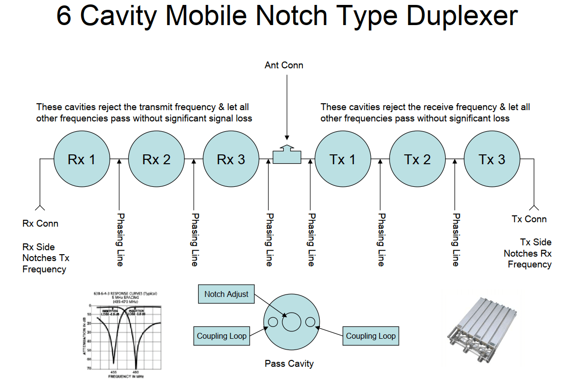
Duplexer design is another subject unto itself, however, we will cover some of the basics. The least expensive duplexer is a mobile duplexer which utilizes notch filters to accomplish the task. A notch filter duplexer will notch only one frequency, so it is tuned to notch the receiver frequency from the transmitter and the transmit frequency from the receiver. (It will also notch frequencies that are extremely close to the frequency to which it is tuned, but most of the time, additional repeaters are on frequencies that do not meet the criteria.) When you add another duplex system at the same site, now the transmit and receive frequencies are different than the ones utilized in the original repeater. The duplexer is incapable of notching the additional frequencies. As you add additional repeaters, there are a whole host of frequencies that need to be notched to keep them out of the original repeater, but the duplexer is only capable of notching the original frequencies and frequencies that are very close to the original repeater. Since the duplexer is no longer protecting the receiver and transmitter in the original repeater from the other repeaters, the interference situation becomes critical and usually the system is overwhelmed by interference.
TO ALIGN THE DUPLEXER: Tune the reject frequencies in all the cavities on the transmit side to the receive frequency and all the cavities on the receive side to the transmit frequency. Then you tune to maximize the return losses on each side of the duplexer to optimize the pass band while minimizing the return losses at the reject frequency.

Base station duplexers are a better design for the above situation, but they still are insufficient. Base station duplexers are typically pass-notch design, so they will work under a more adverse situation. The filters in the duplexer have frequency pass filters which pass the receive and transmit frequencies (including frequencies within a range of 0.5-2MHz of the repeater frequencies) plus they have notch filters that are tuned to the specific receive and transmit frequencies of the repeater. The notch filters contain the limitations enumerated above regarding the mobile duplexer. The pass filters are often broad enough to pass the frequencies of one or more of the additional repeaters. Therefore, the much more expensive base station duplexer is better, but not good enough.
In reviewing the duplexer curves above, it is clear that there is a significant difference in the shape of the curves compared to the notch type duplexer. The pass frequency of the transmit side is actually about a 4MHz passband and the notch frequency is 5MHz above at the receive frequency. When you look at the frequency response curve, the upper end seems to continue to drop towards zero, therefore, the out of band rejection is poor. The low frequency end of the curve seems to be rising as it goes off the screen to the left, but it flattens out as it continues out of the band and eventually returns close to zero. The reverse is true for the receive side of the duplexer where the passband is on the high side and the notch is on the low side. The notch side continues to drop towards zero as you go lower in frequency and on the high frequency side of the response curve, it appears to be rising slowly. Unfortunately, like the other side, the curve flattens out and drops once it is out of band. Although the in-band rejection is superior while in-band, the out of band rejection is not good.
TO ALIGN THE DUPLEXER: Tune the pass frequencies in all the cavities on the transmit side to the transmit frequency and all the cavities on the receive side to the receive frequency. Then you tune to maximize the return losses on each side of the duplexer to optimize the pass band adjustments. Next you tune the notch frequencies to reject the frequency of the other side of the duplexer, so you tune the transmit side to reject the receive frequency and the receive side to reject the transmit frequency. After that is done, you check the return losses on each side of the duplexer to make certain that the return losses are high in the pass-band frequencies and low at the reject frequencies on both sides of the duplexer.
The reasons that multiple radio systems operating on duplexers is a problem:
- Duplexers do not have out of band rejection. Therefore, a UHF duplexer does almost nothing to reject VHF LO, VHF HI, 800Mhz, 900MHz and 220MHz LMR bands or anything else such as microwave, TV broadcast, radio broadcast, etc. The out of band rejection problem is typical for duplexers. The mobile duplexer only rejects one frequency for receive and one for transmit. Therefore, the out of band rejection is non-existent
- Duplexers do not contain any isolators which make the RF from the transmitter travel towards the antenna and not allow reflected power from the antenna to go back to the transmitter which can cause the transmitter to burn out or generate interference by mixing the transmitter signal with the signal from the other transmitters at the site in the final amplifier of the transmitter. The final amplifier will easily mix signals since it operates in a non-linear fashion by design in FM systems that do not need to maintain linear operation. Therefore, an external isolator needs to be added to the duplexer.
- Most duplexers do not have true passband filters. On higher frequency bands such as 800MHz and 900MHz, true passband filters in the duplexer are common. On lower frequencies, true passband filters are very uncommon due to the frequency separation between receive and transmit. In order for the duplexer to have sufficient isolation between the receive and transmit frequencies, usually the filter must be a pass-notch filter which increases the isolation between the receive and transmit frequency, however, it makes the out of band rejection very poor. Therefore, an external passband filter such as a cavity is required which needs to be added to the duplexer.
- Duplexers require one antenna per repeater in a limited antenna space which creates a situation where each of the antennas adversely affects the other antennas in the space. Signal from one antenna will couple to another antenna, thus increasing the signal level of the additional repeaters into the original repeater as well as all combinations of repeaters at the site interfering with each other. As an example, 8 repeaters would require 8 antennas using duplexers, but the same 8 repeaters could use as few as 2 antennas if using a master receive antenna and transmit combining.
- The cost of a quality duplexer along with the external cavity filter and the isolator times the number of channels will be significantly more expensive than using a master antenna system as described below. It is typical for the number of repeaters to grow one or two at a time until the problem is totally out of control. At that time, it is necessary to switch to the master antenna system to alleviate the problems described above. If you can install a master antenna system from the beginning, the ultimate cost will be less than using duplexers, adding the additional cavity filters and isolators to control the interference.
In reviewing the above diagram, each duplexer contains a notch filter to protect the associated repeater receiver from its own transmitter, but it does not contain filters to protect the other receivers from this transmitter. The receiver side of the duplexer contains filters to protect this receiver from its associated transmitter, but does not contain filters to protect the other receivers from this transmitter. This is the problem of not having a master plan to prevent interference.
To overcome the limitations of duplexers, most quality antenna sites use master receive antenna systems and transmit combining. These systems overcome all the limitations of the duplexer systems.
Master Receiver System Overload
Master receiver systems are used to connect more than one receiver to the receive antenna. The design of the master receive system is critical to the performance of the radio system and is a complete subject unto itself. As an example, master antenna systems are used in apartment buildings to feed the TV antenna to the TV sets in the different apartments. If an apartment building had one or more TV antennas for every apartment, there would be numerous antennas on the top of the building. There may not be enough space for all the antennas, the multiple antennas can interfere with each other plus the large number of antennas tends to be unsightly. Overload of the master receiver system in an LMR radio system has a more detrimental effect on radio systems than the interference in a single receiver because it will affect more than one radio system. It affects every radio system that is using the master receive system. It can exhibit both symptoms listed in the section on receiver overload.
When looking at the diagram of the receive system, there are several notable items. The receive filter depicted above is a dual band filter, allowing signals from two different UHF sub-bands (456-460MHz and 466-470MHz) to pass through the filter. (The UHF band is broken into 2 sub-bands. The first sub-band is 450-460MHz where the repeaters receive 455-460MHz and the repeaters transmit 450-455MHz. The second sub-band is 460-470MHz where the repeaters receive 465-470MHz and the repeaters transmit 460-465MHz. This creates a 5MHz offset between the receive and transmit frequencies. In UHF-T Band which is 470-512MHz is used in 11 major cities across the country, the offset is 3MHz. because these frequencies were reassigned from TV use for LMR in the early 1970s. TV channels are 6MHz wide, so when divided in half for receive and the other half for transmit, the spacing was much narrower.) The two filters are connected in “parallel” with the phasing harness (splitting cables that are a specific length based upon the frequency of operations) which allows both sub-bands to pass through to the receiver preamplifier with minimal loss. The preamplifier is a critical design because it needs to have a very low noise figure and a high third order intercept point which allows the amplifier to hear very weak signals and is highly resistant to being overloaded which will cause intermod to be generated within the amplifier. After the 1st amplifier is a 2nd amplifier to increase the gain to drive the many receiver outputs. Then there are quality receiver splitters which divide the signal amongst the numerous outputs to feed the multitude of receivers that need to obtain the receive signal while maintaining a 50-ohm circuit impedance. Each 4-way splitter has -6db loss, so the total splitting loss is -12db. Each amplifier has a gain of +12db, so the total system gain is +12db +12db -6db -6db = 12db.
Here is a slightly different master receive system which will provide for better performance than the first system. There is one stage of amplification, then one stage of splitting the receive signal. Then there is a 2nd stage of amplification and a 2nd stage of receiver splitting. This design requires more amplifiers which increases the cost, but it has better performance because the signal level at the input of the 2nd stage amplifiers is reduced by -6db, the amount of splitting loss for the first 4-way splitter. With the reduced signal level input to the 2nd stage, there is a greater resilience to being overloaded which will create intermod in the receive system. The total system gain is the same as the first example, but it has a 3rd order intercept point that is 6db greater than the first example.
Transmit Combiners & Interference
Transmit combiners are devices that allow multiple transmitters to be connected simultaneously to the same transmit antenna. The design and installation of a transmit combiner system is another subject unto itself. When a transmit combiner is installed, it must be designed for the specific frequencies that are being used. However, the frequencies in use tend to change over time and often the technician who “retunes” transmitter ports on the combiner system does not have the prerequisite knowledge to fully grasp the issues and considerations involved. This causes degradation of the combiner performance and may result in intermod being generated within the combiner system by mixing the signals together that the combiner system was intended to keep separated. There are other issues with transmit combiners including improper design and manufacture, which allows interference to be generated. If the unwanted signals fall on any receiver frequency, it can bother those receivers. If the unwanted signals fall on any transmitter frequency, it can be an unwanted signal heard by many radio receivers around the coverage area of the site. If the interference falls on a public safety frequency, this will wreak havoc with the fire, police or other public safety agency and subject the source of the interference to major scrutiny including potential fines and an order to cease and desist.
In reviewing the block diagram of a low loss transmit combiner above, each channel of the combiner consists of a dual isolator that provides between -50db and -70db of isolation between the forward and reverse directions. (It is called a low loss combiner because it typically has about -2.5db signal loss while combining 5 channels. The combining loss will increase as the frequencies get closer together, so the combining loss will vary by channel and sometimes exceed -3db.) That is because each stage of the isolator provides approximately 25-35db of isolation. Most transmit combiners have dual stage isolators, however, some combiners use single stage isolators and some use triple stage isolators. This keeps the RF signal going in one direction towards the antenna and prevents the signal from going back to the transmitter to cause intermod and overheat the transmitter which can lead to the transmitter failure. The signal enters through port 1 of the isolator and is rotated clockwise to port 2. Any reflected power from the antenna enters port 2 of the isolator and is rotated to port 3 where it is dissipated in the 50-ohm load. No reflected power enters port 3 unless the 50-ohm load is bad, so no reflected power never makes it back to port 1 where the transmitter is located. The signal then passes through a high Q cavity which provides approximately -15db or more isolation between all the channels that meet at the star junction. The star junction is where all the channels meet and the cables between the star junction and the cavity are phasing lines which are critical length cables. Each cable represents ¼ wavelength at the frequency of the channel times the velocity factor (the speed at which the signal travels in the cable relative to the speed of light in a vacuum) of the coaxial cable being used plus the electrical length of the loops in the cavity. This creates a high amount of rejection for frequencies that are more than a 200KHz away from the channel and effectively looks like an open circuit to those frequencies due to the ¼ wave section. However, the junction has a limited bandwidth, so all the frequencies must be within a certain percentage of frequency compared to all the other frequencies. (A cavity will act as a short circuit to frequencies removed from the frequency to which it is tuned. The quarter wave section changes the short to an open circuit at the junction, so each channel looks like an open circuit to other frequencies.) Another issue is the type of materials that are used for the cables, connectors, star junction, etc. It is possible for the transmit combiner to generate intermod if the wrong materials are used for the various components, especially the connectors. It is a known fact that nickel plated connectors cause intermod on combiners at 800MHz and 900MHz, therefore, they should not be used in those devices.
TO ALIGN A COMBINER CHANNEL: With a tracking generator, tune the cavities to the transmit frequency of the channel on the combiner. This can be done in several different ways. First, you can disable all the transmitters into the combiner and feed a signal through the combiner port that needs alignment from the input to the output, tuning the cavity to the transmit frequency for lowest loss. The second (and better) method is to use the tuning port which some combiners have and tune for a notch out of the test port on the correct frequency. The third method is to use the tracking generator in the return loss mode to look at the output of the combiner (with all transmitters disconnected) and tune the cavity to maximize the return loss at the output.
TO ALIGN THE ISOLATORS: When changing the frequency of a port, the isolators need to be retuned if the change in frequency is more than a few megahertz unless the isolators are broadband and / or not tunable. To tune an isolator to a frequency, tune the return loss of the input port #1 of the 1st stage to maximize the return losses. Then tune the output port #2 of the 2nd stage of the isolator to maximize the return losses. Then, sweep the isolator with signal injected into the input and looking at the output to minimize loss and flatten the response across the band. Last, turn the isolator around and feed signal into the output and look at the input while tuning the notches on each stage to the transmit frequency. This will make the isolator perform well.
This block diagram shows a completely different design for the transmit combiner. This design has the advantage of being expandable to any number of ports with some limitation. Also, since the critical length phasing cable is within each channel, there are no frequency limitations from a bandwidth perspective provided each channel is the required minimum spacing which is about 500KHz. Each port requires the use of two cavities which increases the cost per port. The transmitter is connected to the input of the dual isolator which provides between -50db and -70db of isolation between the forward and reverse directions. The signal passes through the 1st Cavity A which is tuned to the transmitter frequency at which point it reaches a T junction which allows the signal to go either of two directions. The phasing cable is connected to one end of the T junction and the other end goes to the 2nd Cavity B T junction. The 2nd cavity is a notch filter which is tuned to the transmit frequency that acts like a short circuit to the phasing line, representing an open circuit at the 1st T junction at the first cavity. Therefore, the transmit signal views the path to the 2nd cavity to be high impedance so the signal goes up towards the antenna which is a 50-ohm circuit. The lower port connects to the next transmit combiner panel with any length cable to the upper port of the next combiner panel so that it can expand to any reasonable size subject to the limitations of the frequency response of the antenna which must be able to work at all the transmit frequencies and the fact that the loss increases by 0.2db for every panel above the transmit combiner port in the system. On the bottom port of the bottom panel, a 50-ohm load will terminate the port to maintain the proper impedance and performance of the notch filter.
TO ALIGN A COMBINER CHANNEL: Feed a signal into the channel input and look at the channel output. Place a 50-ohm load on the 3rd port that connects to lower ports on the combiner. Tune cavity A center the response curve on the transmit frequency at the output and then tune cavity B to reduce the losses. Cavity B has a minor affect on the pass frequency, but mostly it tunes the ¼ wave section to look like an open circuit to cavity A, so it reduces the amount of transmit signal going down towards other channels in the combiner and increases the amount of transmitter signal going up towards the antenna.
TO ALIGN THE ISOLATORS: See the procedure for aligning isolators on combining system I.
The above block diagram depicts a 4-channel hybrid transmit combiner. It uses the same isolators as the other two combiners, but the combining is performed by hybrid balance networks that isolate two inputs by a minimum of -20db. Each stage of hybrid operation combines two transmitters together and have -3db loss. Transmitter 1 & 2 are combined by hybrid #1 while transmitter 3 & 4 are combined by hybrid #2. Hybrid #1 and hybrid #2 are combined together by hybrid #3. The great feature of this combiner is that it is not very frequency sensitive and will combine adjacent channels or frequencies that are 10MHz away without additional loss, but it tends to have high losses compared to a low loss combiner. Two transmitters are combined with about -4db loss, 4 channels with -7db loss and 8 channels with -10db loss. With this type of combiner, the 8-channel combiner will cause a 100 watt transmitter to have an output from the combiner of only 10 watts, a significant reduction of ERP.
There are other designs of transmit combiners, all of which have some common elements to the two types of combiners described above. Each of these other designs achieve the isolation between transmit channels while protecting the transmitter from failures in the antenna system from causing premature failure of the transmitter.
This combiner generally does not need to be aligned after leaving the factory unless there is some type of failure in the combiner. The isolators and hybrid is fairly broadband.
Intermodulation (IM) Suppression Panels
Another type of interference suppression device is the IM suppression panel which is designed to keep the transmitter safe from a failed antenna system and designed to keep the transmitter from becoming a source of radio interference. The device consists of a single, double or triple stage isolator and a low pass filter. Although isolators are marvelous devices that do a great job of protecting the transmitter from a bad antenna system while reducing the potential for intermod, it has one flaw which can come back and bite the not too savvy technician who does not realize that the isolator that is connected directly to an antenna can and will generate a 2nd harmonic interference which is twice the transmitter frequency. The low pass filter (transmitter #1) will take out the 2nd harmonic because it is tuned to start rolling off above the transmitter frequency. The advantage of the traditional IM suppression panel is that it has a wide frequency response due to the low pass filter on the output which is great for a frequency agile transmitter. Since most radio transmitters are not frequency agile, a better plan is to use the isolator with a cavity which is a bandpass filter (transmitter #2) instead of a low pass filter which will suppress more noise from the transmitter and more spurious outputs because it suppresses both.
TO ALIGN THE COMBINER: The first IM panel does not need alignment unless you are moving the frequency some distance in megahertz where you are starting to get into the rolloff frequency of the low pass filter which is not likely. The 2nd IM suppression panel has a cavity output which needs to be tuned to the transmitter frequency by feeding a signal into the transmitter #2 input and looking at the output of the cavity while tuning the cavity to the transmitter frequency. This can be optimized by looking at the return losses at the output port and adjusting the tuning slightly to optimize.
TO ALIGN THE ISOLATORS: See the procedure for aligning isolators on combining system I.
Coaxial Cables and Connectors
Another important issue when attempting to control antenna site interference is to install your equipment using the correct cables. Too often the cables used to attach the receiver and transmitter to the antenna system and the antenna system cables are substandard. This creates a situation of interference that is sometimes difficult to trace. By implementing proper site standards, problems that will plague the site can be easily avoided.
Almost all radio systems operate with 50-ohm antenna systems. The main exception is the TV industry which operates on 75-ohm circuit impedance. It seems simple to expect that a 50-ohm antenna systems uses 50-ohm cable, connectors, filters and antennas. However, this is often not the case. Recently we were troubleshooting a wireless camera feedback system installation that would not provide proper coverage in a TV studio. The transmitter was 50-ohm and it was installed under the supervision of the chief engineer who was also a ham radio operator. You would think that they would be familiar with the differences between 50-ohm and 75-ohm circuits, but this was not the case. There was an interesting mixture of 50-ohm and 75-ohm components of cable, connectors, power dividers, DC power injectors, jumper cables and adapters that made the system completely inoperable. The studio engineers were clueless as to the problem, yet it took us less than 30 minutes to identify the problems and recommend the proper solution.
For those who are not familiar with the differences, let’s discuss a little theory. The impedance of a coaxial cable is based upon its physical dimensions. The impedance can be determined by the formula of z = 138 / square root of the dielectric constant x log10 (inner diameter of the shield / outer diameter of the center conductor). Translated into English, the 50-ohm cable will have a larger diameter center conductor than the 75-ohm cable. Therefore the experienced eye can look at the cable or the connector and see if it is a 50-ohm or 75-ohm device. Most people do not realize that you can plug a 75-ohm BNC or Type N male connector into 50-ohm female connectors. Just because it can be done does not mean that it will work. The 75-ohm male center pin is smaller diameter than the 50-ohm center pin, so when you plug it into the 50-ohm female, you have a capacitive connection in the connector because the male center pin does not make contact with the female center pin.
A similar effect can happen with the 75-ohm cable having a 50-ohm Type N male connector installed. It seems silly that someone would install the connector in this situation, but some people do not notice the difference, especially when you use a solderless quick assembly connector where the cable is stripped and inserted into the back of the connector which is supposed to grip the center conductor with a female contact receptacle that is intended to be solderless. Unfortunately, the two do not make contact, so we have another capacitive connection that has loss in excess of 20db instead of about 0.1db for the connection. If you happen to install a 75-ohm cable like we did on one occasion when the customer gave us the cable that they had in storage for many years to install and no one looked closely at the cable before we had 4 men spend all day to pull the cable through crowded conduits, you may have to fix the problem. We found a 75-ohm to 50-ohm balun transformer made by Anzac part number TPX-75-4 that provided proper conversion between the two impedances. The problem was complicated by the fact that the 75-ohm cable and connectors had been discontinued, so locating the connectors for the cable became another search and rescue event. So, let’s keep everything 50-ohm for your non-TV / Video connections in the future.
Another big issue is to use a high quality coaxial cable. Cables with 50-75% braid should be thrown in the trash. A high quality cable will have a 95% or greater braid which we will never use, because if you want to control site interference, you need your cables to be double shielded or 100% shielded. Tower sites wired in 95% shielded cables can couple significant energy between cables. Let’s look at the math:
- A 100 watt transmitter is +50dbm
- A good receiver will hear down to -121dbm
Therefore, the difference between the two is 171db which represents the system gain. If you have a 95% (physical coverage) shielded cable, the amount of signal that leaks out of the cable is at the level of -55dbc. If you place 50 feet of the transmitter in a cable tray and lay the receiver cable next to the transmitter cable, you can expect the transmitter signal to get out of the cable at a level of -55dbc (-55db below the carrier level in the cable) and get into the receiver cable at -55dbc for a net signal level of -110db below the transmitter signal which is 61db greater than the weak signal that could be heard by the receiver before your transmitter started to desense your receiver. If you bundle a dozen coaxial cables in this situation with cable ties, you now have each one of the cables coupling into the other causing an almost hopeless interference situation. It is time to start being smart about using coaxial cables. The following chart gives 5 examples of shielding characteristics of coaxial cables:
| Type No. | Cable Type | Shielding Effectiveness | Cable Example |
| 1 | Single 95% Braid | -55dbc | RG58/U |
| 2 | Single 60% Braid + Foil Wrap | -90dbc | RG6 Dual Shield |
| 3 | Double 95% Braid | -95dbc | RG142, 400 |
| 4 | 2 x 60% Braid + 2 x Foil Wrap | -110dbc | RG6 Quad Shield |
| 5 | Solid Shield Cable | -150dbc | AVA5-50 |
As you can tell from the chart, there is a significant amount of difference in the leakage of different coaxial cable designs. Using the correct coaxial cable will prevent horrible interference problems from being generated. It is not only the cable that you use yourself, it is also the cable used by others at the site that determine how much RF is leaked around the building and is available for coupling into your radio system.
Cable type 4 is commonly used in the cable TV industry. RG6 quad shield cable which has a aluminum foil for the 1st shield, 60% braid for the 2nd shield, aluminum foil for the 3rd shield and 60% braid for the 4th shield has replaced most of the poorer coax cables in the cable industry because they had too many problems with signal leakage.
Times LMR400 and Belden 9913 (which are cable type 2 above) can be used outdoors, but they can only be used under the proper situation. These are aluminum foil cables that have a limited shield woven over the aluminum foil. Aluminum cables should be used sparingly at a crowded tower site due to the propensity of aluminum to make poor contact with the connector, thus becoming a source of intermod. Also, these cables when run up a tower can easily develop micro cracks in the aluminum foil shield. As the cables move in the wind, they will generate site noise that can be heard in the radio receivers due to the woven braid moving across the aluminum foil. When under transmitter power, arcing can occur in the cable which will generate a large amount of site noise. If used as an outdoor cable, it must be secured to the tower leg or use some other method of being supported over virtually 100% of the cable length to prevent the cable from being a noise generator. These cables should never be used on a transmit line where there is more than one frequency in the cable due to the intermod potential of the cable. They are much safer to use on receive cables, but are not immune from creating problems on receivers.
All cables on the tower must be rated for outdoor use. Commscope (previously Andrew) Superflex (which is cable type 5 above) is NOT an outdoor cable and should never be used outdoors even though I have seen it hundreds of times. It has a thin jacket which can become nicked easily, then water will get under the cable jacket and travel down the shield due to the spiral corrugations and then attack the connector which is vulnerable to being water soaked. Proper outdoor cables are Commscope AVA5-50 7/8” hardline cable or LDF4-50 ½” hardline cable, Cablewave LCF12-50J ½” hardline cable or LCF78-50JA hardline cable or Eupen cables such as EC5-50-A 7/8” hardline cable or EC4-50 ½” hardline cable. (These are all cable type 5 above.) The connectors need to be properly installed according to the factory recommendations and properly sealed against the weather. (We use Raychem WCSM 34/12 heat shrinkable tubing or other correct size heatshrink for the cable with sealant to make a waterproof connection. After thousands of connector installations, we have yet to have one of the seals fail and allow water into the connection.) Cables must be properly secured on the tower with cable clamps to prevent damage to the cables and generation of intermod products.
Jumper cables inside the building should all be either double shielded on receive or 100% shielded on transmit. Cables such as RG-142 double shielded silver plated Teflon cable are a great and flexible cable for receivers and so is RG223 double shielded cable, but should not be run too great a distance due to the amount of cable loss. (Both of these cables are type 3 above. Also, RG-400 is a stranded center conductor version of RG-142 which has a solid center conductor and RG-400 is more flexible than RG-142 cable.) It can be used on transmitters if the run is fairly short due to the shielding, signal loss and power handling capability. RG214 double shielded silver plated cable, but it is not 100% shielded and has about -5db loss per 100 feet of cable. Times Microwave LMR-240, LMR-400 (cable type 2 above) or preferably Commscope Superflex (cable type 5 above) should be used on transmitters with properly attached connectors due to the 100% shielding, but the aluminum cables should only be used on a single frequency transmitter and NEVER on the output of a transmitter combiner. In summary, the selection of the proper cable is a compromise between size, loss, connector selection, flexibility, weather resistance, power handling capability and maximum cutoff frequency of the cable. There is no single answer as to which cable is the proper selection for every situation, however, it is best to err on the side of quality to avoid having chronic problems.
There is a website https://www.rfcafe.com/references/electrical/coax-chart.htm that has a lot of good reference material on coaxial cable, connectors and many other RF subjects.
Connector types are always a consideration at tower sites. The PL259 / SO239 UHF connector should never be used at a tower site because it is not a 50-ohm connector and it leaks like a sieve. Any equipment with such a connector should be replaced with a different piece of equipment with different connectors if the connectors cannot be replaced. BNC connectors are good 50-ohm connectors, but should be avoided if possible due to the ground connection being a bayonette instead of being a threaded connection. The TNC connector is a better choice, but is not a popular connector and very little tower site equipment uses the TNC. The Type N connector is the most popular and is a great 50-ohm connector, but it has a limitation as to the power handling capabilities due to the small size of the center pin on the connector which is even worse for the 75-ohm versions for TV / Video systems. The 7/16” DIN connector is a better (much larger and more expensive) connector which is preferable in higher power situations and on tall towers (over 200 feet) due to the ruggedness of the connector and the low PIM rating. One of the new connectors on the scene is the 4.3-10 connector for similar reasons to the DIN connector, but a bit smaller in size and more economical than the DIN.
Aside from the type of connector, there are as many different manufacturers of connectors as Carter has pills. Some cable manufacturers such as RFS Cablewave, Commscope, Eupen, Trilogy and Times Microwave will manufacture connectors for their cable which is usually a good choice for their cable. There is a huge difference in the quality of the connector from different connector manufacturers for smaller coaxial cables. RF Industries seems to be readily available and cheap, but unfortunately, usually poor quality. Amphenol is an OK connector, but if you want a real good quality connector, you need to use Kings or Delta, but you will pay the price.
Just remember, you can be penny wise with your connectors, but you will be dollar foolish with the result. Failures of connectors which result in system failures with many trips to the mountain tops will plague your installation if you use a cheap connector or if you use poor connector installation techniques. There never seems to be enough time to install a radio system correctly, but there is all the time you need to keep repairing the installation over and over again. If you spend the time and money up front to do the job right, it will pay dividends for many years to come and reduce your overall maintenance costs.
Tired of fighting radio interference? Let MRA Solve Your Interference
Tower Hardware
Tower hardware is a prime source of radio interference. That is because any two metals in poor contact with each other can create a non-linear junction that will mix radio signals together like the mixer in a radio. However, since there are no filters on the mixer, it can mix anything with anything and produce large quantities of spurious signals. This type of action requires a sufficiently strong RF field which exists on radio towers, especially when there are many radio transmitters using the tower or on a nearby tower. This includes rusty hardware on a radio tower and loose hardware that is making poor contact with the tower and moves around in the wind. If the loose hardware is part of the tower grounding, it can become a safety hazard, a lightning rod without a way to dissipate the energy without sending it through the electronic equipment and become another source of radio interference.
Chain Link Fence, Barbed Wire and Razor Wire
Each of these items are used for site security. However, when exposed to a high RF field, they represent two metals in poor contact with each other. Chain link fence is the least offensive because it seems to be under tension most of the time. If the fence is damaged, then the wraps of chain link are loose and have a greater potential for causing interference. Barbed wire is in poor contact with itself as the barbs are not welded to the main wire and it is typically in poor contact with the mounting brackets that hold the wire in place. Razor wire is always loose and in poor contact with the fence as well as the barbed wire. The higher the power of the radio transmitter, the greater the chance that it will generate interference, so when a TV or radio broadcast transmitter is at the site, grounding of the fence and its components is essential.
Tired of fighting radio interference? Let MRA Solve Your Interference
Belden RG8 Coax Techdata.pdf
Belden RG11 Coax Techdata.pdf
Belden RG58 Coax Techdata.pdf
Belden RG142 Coax Techdata.pdf
Belden RG174 Coax Techdata.pdf
Belden RG178 Coax Techdata.pdf
Belden RG188 Coax Techdata.pdf
Belden RG213 Coax Techdata.pdf
Belden RG214 Coax Techdata.pdf
Belden RG223 Coax Techdata.pdf
Belden RG303 Coax Techdata.pdf
Belden RG316 Coax Techdata.pdf
Belden RG402 Coax Techdata.pdf
Belden RG405 Coax Techdata.pdf
Belden 9913 Coax Techdata.pdf
Commscope Cable LDF4-50.pdf
Commscope Cable AVA5-50.pdf
Eupen EC4-50 Coax Hardline.pdf
Eupen EC5-50 Coax Hardline.pdf
RFS LCF12-50J Coax Hardline.pdf
RFS LCF78-50JA Coax Hardline.pdf
RFS SCF12-50J Coax Superflexible.pdf
Times LMR-240 Coax.pdf
Times LMR-400 Coax.pdf
Times Microwave TL-16 Complete Catalog-R.pdf)
Commscope Connector for LDF4-50.pdf
Commscope Connector for AVA5-50.pdf
Eupen Type N for EC4-50.pdf
Eupen Type N for EC5-50.pdf
RFS Type N-M for LCF-12.pdf
RFS Type N-M for LCF78.pdf
Pasternack Article 12 Tips and FAQs for Selecting the Right Coaxial Cable.docx
Delta 7-16 Din Catalog.pdf
Delta BNC Catalog.pdf
Delta TNC Catalog.pdf
Delta Type N Catalog.pdf
Harbour Industries Coax Catalog.pdf
L-COM-Coaxial-Cabling-Tutorial.pdf
Trilogy AC012J50 Hardline Cable.pdf
Trilogy ACC012J50 Hardline Cable.pdf
Trilogy AP6012J50-BK Hardline Cable.pdf
Trilogy Cross-Reference Chart.pdf