INTRODUCTION
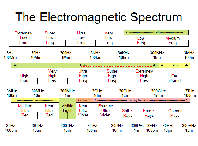
Like any other technology, the history of radio is one that developed over time. Radios started off being spark gap transmitters which contained radio energy over a wide range of frequencies. Eventually a range of frequencies became referred to as a band of frequencies which makes sense when you look at the frequency chart above. As an example, visible light represents a band of frequencies that are not radio waves, but they are nonetheless an electromagnetic wave. Radio transmissions are in another range of frequencies which are typically broken down into many different bands such as VHF, UHF, SHF and many more. Each of these bands are broken down into many sub-bands and each of the sub-bands are considered to be a different band. Over time, it was discovered that different bands of frequencies behave differently or have different propagation characteristics which makes the traveling of the radio wave behave differently as they travel across the land or sea. For those reasons, it was determined that certain ranges of frequencies (bands) worked more favorably for certain types of communications while other frequency bands worked better for other purposes.
Frequencies within the radio spectrum are continuous from the lowest frequency where radio waves start around 30KHz to the highest frequency used in radio which is around 300GHz. In order to make the most efficient use of the spectrum, the FCC has designed certain frequencies for specific uses and determined how the radio channels should be assigned. The scheme for assigning channels varies by frequency band. When radios first started, technology was far more primitive than it is today. At that time, it was difficult to make radios at higher frequencies, so the lower frequencies bands were released by the FCC for use while the VHF high band and UHF were not used.
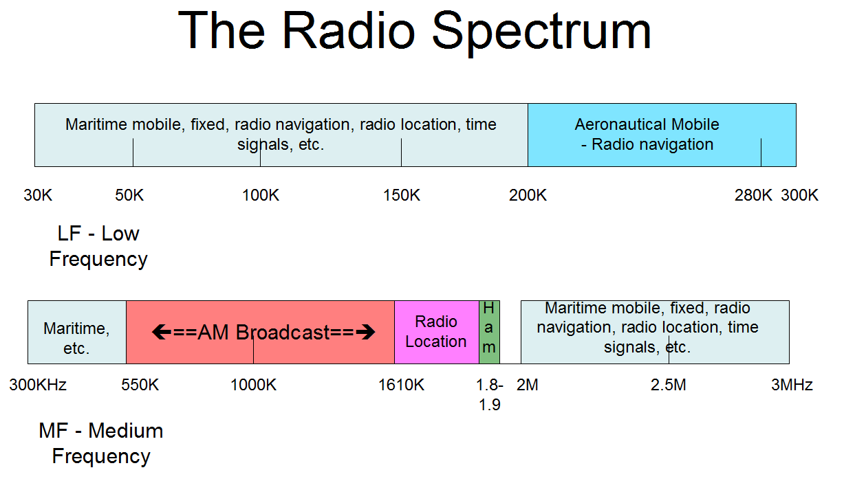
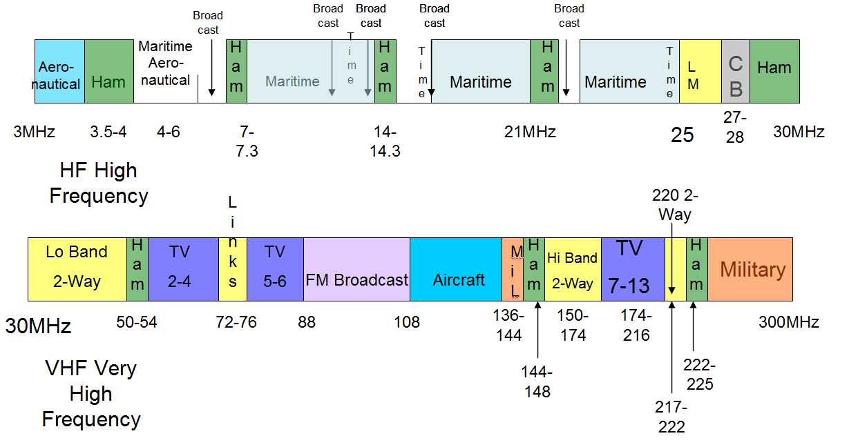
Radio and TV manufacturers need some set of standard by which they would design and manufacture equipment for the public so that when a broadcast radio listened to 930KHz AM, the radio station was decoded by the radio receiver properly or when a TV set was manufactured by RCA, it would receive the TV signal from a Collins TV transmitter. Therefore, standardization was the key to being able to manufacture radio equipment just like standardization in all other industries allowed for the rapid expansion of the industrial revolution. The following chart depicts the various uses of the radio spectrum.
In referring to the chart above, the FCC designated different bands of frequencies to different uses. For brevity, only the frequencies below 300MHz are shown in the chart. Please refer to the FCC licensing page on our website for a more comprehensive chart.
AM BROADCAST INTERFERENCE
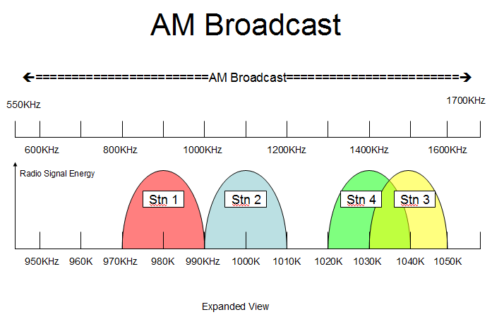
AM broadcast radio operates between 550KHz and 1700KHz per the frequency chart below. In order to be able to receive an AM station, you need to know how wide a range of frequencies is contained in the radio signal so you know how wide the receiver needs to be to receive the entire transmission of the station you want to hear and how narrow the receiver needs to be to avoid hearing the station on the next closest frequency. If the receiver is made very wide, it receives multiple radio stations at the same time. If the receiver is made too narrow, it will cut off some of the transmission which will cause distortion of the radio signal and your “HiFi” music becomes “LoFi” and does not sound as good as it should sound. In the example in the diagram below, the radio signal is 20KHz wide for each of the broadcast stations. Station 2 is on 1000KHz (the FCC always refers to the frequency at the center of the radio signal) with a 20KHz bandwidth, so the signal extends from 990KHz to 1010KHz. Station 1 is on 980KHz with the same 20 KHz bandwidth, so the signal extends from 970KHz to 990KHz. The signals of station 1 and station 2 do not overlap, so in theory, there is no interference between stations. If the receiver is designed to receive exactly a 20KHz wide signal, it will receive the entire signal provided the receiver frequency exactly matches the transmit frequency. If the receiver drifts frequency down by 1KHz, the receiver will receive from 969KHz to 989KHz, thus eliminating the portion of the signal from 989KHz to 990KHz. This will cause a loss of fidelity of the received signal and cause signal distortion. A similar effect will happen if the transmitter moves up 1KHz in frequency so the transmitter will occupy from 971KHz to 991KHz. In that case, station 1 will overlap station 2 by 1KHz causing interference to people attempting to listen to station 2 and the people who are listening to station 1 will have a loss of fidelity because part of the signal is missing. The problem gets even worse if the transmitter drifts up while the receiver drifts down because now the frequency error is the sum of the transmitter drift and the receiver drift.
As a practical matter, the transmitter signal is normally a little less than the receiver bandwidth. This allows for the transmitter to drift frequency a little and for the receiver to drift frequency a bit more. All radios have frequency drift, so it is essential to design the transmitter bandwidth to fit within the channel and allow for things to go wrong which will happen in real life situations.
Looking at station 3 and station 4 above, the two stations overlap each other. So the $64,000 question is why would you place stations on the air in this situation? The first thing that you should notice that there is more energy at the center of the radio transmission and the energy falls off as you move away from the center. This means that the interference in the overlap area is not as bad if the two stations were on the same frequency. (By having only a portion of the radio signal overlap where the energy in the signal is minimal, the overlap problem is reduced so that the normal physical separation between stations can be less than if they were actually on the same channel.) If these two stations were in the same market area, the two stations would cause horrible interference to each other and neither station could be heard properly under most conditions. This is due to the overlap between 1030KHz and 1040KHz which is the area that has the lime green color. However, if one station is in Los Angeles and the other station is in San Francisco, they are far enough apart that they will not interfere with each other under most conditions. However, in the AM broadcast band, some stations can be heard for hundreds or thousands of miles away at nighttime when the radio propagation changes considerably, especially during certain times of the year. Therefore, this situation will not work under all conditions. That is the reason that many AM radio stations will reduce power at night and change their antenna pattern to beam more energy in certain directions and less energy in other directions to protect other radios stations on the same frequency or adjacent frequencies.
VHF RADIO BAND INTERFERENCE
Adjacent channel interference also occurs in land mobile radio. There are many stations that become licensed with overlapping channels, but are far enough apart that most of the time they do not interfere with each other. However, there are situations that are considerably more detrimental. We will examine several different situations that occur on the land mobile radio bands so that you can understand what is happening under different situations.
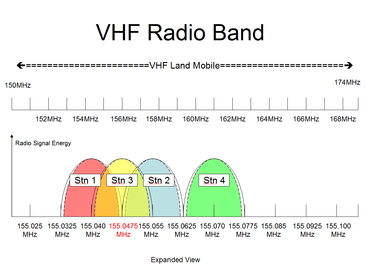
In the VHF radio spectrum, channels were spaced 15 KHz apart. Referring to the diagram above, each channel is 15KHz spaced from the next channel if you ignore the yellow station 3 channel. The radio signal is only 11KHz wide (depicted by the longer dashed line with the red, blue and green color fill. If you ignore the yellow channel, this creates a small guard band between channels so that the receiver can be a little less than 15KHz wide and still only receive the transmission from the green Station 4 signal on the frequency 155.070MHz which is 11KHz wide.
In VHF, channels are 15KHz wide on 7.5KHz centers. This means that each channel overlaps two channels; one on each side of the channel you are attempting to use. Referring to the diagram above, station 3 is on the frequency 155.0475MHz. If that is your radio system, you overlap the channel below on 155.0400MHz (station 1) and the channel above on 155.0550MHz (station 2). This means that about 50% of your transmission will adversely affect the channel below your frequency and the almost 50% of your transmission will adversely affect the channel above your frequency. When channels are assigned in the VHF frequency band, it is necessary to look at all 3 frequencies to see what kind of effect there will be to the existing users on all 3 channels in order to know how the new user will adversely affect them and whether your new radio system will operate without severe interference from any co-channel user and the adjacent channel users. Most of the VHF radio band is set up this way, so it is a common situation to have adjacent channel interference.
UHF RADIO BAND INTERFERENCE
The UHF Land Mobile Band is 450MHz to 470MHz. The following example deals with GMRS and FRS radio frequencies, but this is not the only example of adjacent channel interference.

Within the UHF radio spectrum, all channels were traditionally spaced at 25KHz intervals. However, since 2013, the majority of channels have been arranged with 12.5KHz separations. As illustrated in the above diagram, each channel is positioned at a 12.5KHz interval from the subsequent channel, despite the frequencies not being sequential. A significant portion of the GMRS channels span 20KHz, inciting overlap with neighboring channels. By employing a 12.5KHz bandwidth, a modest guard band is generated between channels, enabling the receiver to be slightly less than 12.5KHz wide, while maintaining the reception quality from individual channels.
When an individual communicates on overlapping channels within a radio’s range, adjacent channel interference occurs, attributable to the authorization of wideband 20kHz signals for GMRS. The FCC has modified its regulations to permit narrowband 11kHz signals on GMRS frequencies, without mandating a universal switch to narrowband. It is clear that no overlap exists between narrowband signals, eliminating adjacent channel interference if all users operate on narrowband. However, as the transition to universal narrowband usage will be gradual, adjacent channel interference between GMRS and FRS persists.
TV STATION INTERFERENCE
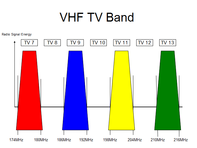
TV stations also have adjacent channel interference issues. Adjacent TV channels are not assigned to TV stations in the same geographic area. Referencing the diagram above, there are TV stations on channels 7, 9, 11 and 13 which represents the TV stations in the Los Angeles area. Channels 8, 10 and 12 are not assigned and create a buffer between TV stations. Looking at the transmitter signals, the TV signal has a lot of energy over most of the TV channel, but the energy starts decreasing its energy output as the edge of the TV channel is approached. The FCC rules require the TV station signal at the edge of the channel to be below a certain level relative to its total output. Below the reference line, the signal continues to get wider than the actual channel. This means that the TV transmitter will produce some energy that goes into the adjacent channel. Since the TV station typically transmits 10,000-50,000 watts, the “weak” portion of signal that falls into the adjacent channel is actually quite significant. If two adjacent channel TV stations are in use in the same geographic area, the lower level signals may interfere with the adjacent channel, especially when the desired TV station signal is weak and the undesired TV station signal is strong. Unlike the Los Angeles area where all the TV stations are in almost the same location (Mt Wilson), in most cities the TV stations are in different locations throughout the city which makes the signal strong from one station and much weaker from another station, so that this condition is quite common in many cities.
Wi-Fi SYSTEM INTERFERENCE
Another example of adjacent channel interference is with the Wi-Fi channels assigned by the FCC. Wi-Fi is used by your computer system, TV sets, routers, Bluetooth and other devices that are all connected together.
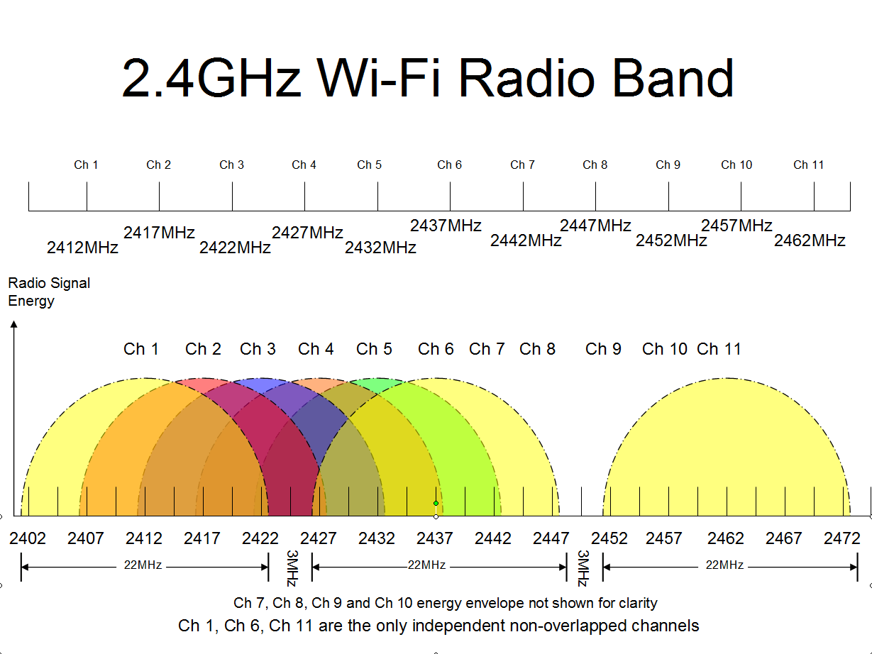
In the diagram above, the center frequency of each channel is listed in the upper level of the chart. However, each of the channels are 22MHz wide, so channel 1 is 2401MHz – 2423MHz, channel 6 is 2426MHz – 2448MHz and channel 11 is 2451MHz – 2473MHz. With 3MHz in between each of the channels, there is no overlap of channels and there is a good sized guard band between channels so that they do not interfere with each other. However, the remaining channels have overlap in the channels which cause interference if they are in range of each other.
- Channel 2 overlaps most of channel 1 and about 20% of channel 6.
- Channel 3 overlaps about 45% of channel 1 and about 30% of channel 6.
- Channel 4 overlaps about 30% of channel 1 and 55% of channel 6.
- Channel 5 overlaps a small amount of channel 1 and about 20% of channel 6.
Therefore, in order to utilize all the channels, there must be physical separation between channels that interject physical barriers which create signal loss that is significantly greater than the signal loss between the Wi-Fi system and the device that is attempting to use the Wi-Fi.
SUMMARY
The above examples depict many examples of adjacent channel interference. However, these are not the only examples of adjacent channel interference. If all of the examples of adjacent channel interference were discussed, this article would be at least 10 times as long. We have attempted to bring to your attention the examples to which many of you can relate and get the basic understanding of the situation. If you have a blaring example of adjacent channel interference that you think would help, please file a comment and we will see if we can add the example to this article.