Land mobile radio (LMR) started in the 1930s and has made a lot of progress since that time. Originally all LMR radios were one-way radios, because they could only talk in one direction. The one-way radios would receive a message in the vehicle where a receiver was located and the dispatch (from typically a police station) would have a radio transmitter to talk to the police cars. Eventually, technology advanced and it became practical to have a two-way radio so that the vehicles could talk back to the police station. As the technology continued to advance, it became practical to install two-way radios for other uses including fire, public works, transportation, agriculture, industrial and normal business activity.
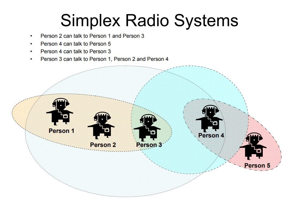
When radio started, the radio transmitter was located at the police station. The signal traveled as far as it could until it could not travel any further. With simplex radio systems, each radio is in a different location and therefore, has a different area of coverage. The above diagram depicts this situation where person #2 can talk to person and person #3, person #3 can speak to person #2 and person #4 while person #5 can only talk to person #4. This creates a situation where it is necessary to relay the message from one person to another to get from person #1 to person #5. Soon, it was determined that if the radio antenna was placed at a higher location, the signal would travel a greater distance than when the antenna was lower. This caused the police to install towers or other mechanical structures to raise the height of the antenna so that the base station could talk further than the mobile radios.
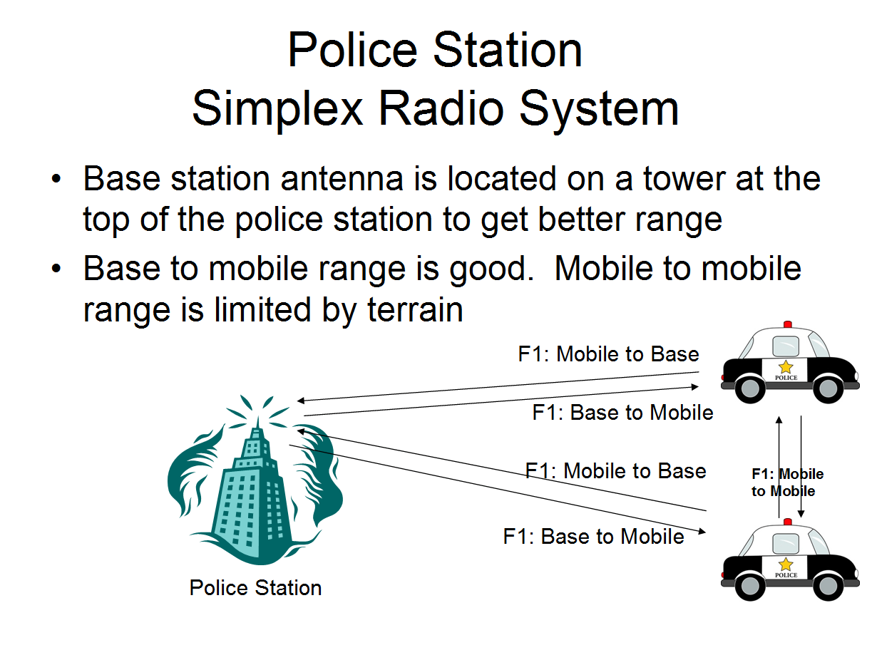
Unfortunately, the police station was not always located where it was possible to raise the antenna to a height that was required to get all the radio coverage that was required. This need caused the birth of the remote controlled base station, which is a radio that is located at a higher location (typically a tall building, hill or mountain top) so that it gets a significantly greater range than if the radio was located at the police station. However, there had to be a method of extending the microphone, speaker and the Push-To-Talk (PTT) function back to the police station. Therefore, necessity being the mother of invention, the remote control equipment was developed.

With the increased range of the remote base station, the station could talk to the vehicles at a much greater distance. However, this did not solve the problem of the mobile units being able to talk to other mobile units. They still have the same limited range because they were huddled amongst the clutter of the city buildings. The remote base station was out of the clutter by being at a high location.
There are some type of radio system operators that do not want the mobile radios to be able to speak to each other. A typical example of this type of operation is for taxi dispatch. Taxi operators tend to argue with each other when they can talk to each other. Often, they get upset because the dispatch assigned the call to another driver when the first driver feels that it was more appropriate to give the call to himself. By having a radio system where the drivers cannot hear to each other, these issues are eliminated. This type of situation applies to other transportation companies who operate on a commission basis for each run that they make. To resolve this problem, the base station transmits on frequency B and receives on frequency A. The mobiles talk on frequency A and receives on frequency B. Therefore, the mobiles talk to the base and the base talks to the mobiles, but the mobiles cannot talk to each other. Now the question was how to effectively provide good range for both mobile to mobile and mobile to base? Hence, the concept of the repeater was born.
The repeater system was a revolution in LMR because the mobile units were able to talk with the same range as the base station. In reviewing the diagram, all mobile units and the base station at the police station transmit on frequency A and receive on frequency B. The repeater requires the use of two frequencies, one for transmit and one for receive, otherwise known as a channel pair. The repeater receives the transmission from the base station in the office or the mobile radios by listening on frequency A, the same frequency that was used by the radios to transmit. Whatever the repeater hears is rebroadcast on frequency B, the other half of the channel pair. All the radios listen on frequency B, so they are listening to the repeater transmitter (which is located at some high site which will produce better coverage than the mobiles talking directly to each other) and not directly to the transmitter of the mobiles and portable units. With the repeater, all the mobiles (and hand-held portable radios which became available in the late 1940s) can get the same range as the base station at the police station. The same principal applies to any other entity that chooses to use radios as the police dispatch.
Some entities require the use of more than one channel (or channel pair) for their operations. Radios have long had the ability to have more than one channel, but in the early days of radio, it was very costly, so most entities that used radios only had one channel. If the radio did have more than one channel, there was a switch on the radio to change to channel 2, channel 3, channel 4, etc. However, the radio only works on one channel at a time and anything said on the channel that your radio has selected is heard (if you are in range of the signal) and anything said on any other channel is not heard unless you change channels manually.
The repeater system works well for all the radios to talk to each other. However, in certain situations, it is important for the base station to be able to talk and override the mobile radios. If you examine the normal repeater system, the base station is nothing more than a mobile radio with a power supply that talks into the repeater just like any of the mobile radios. However, if you realize that some mobile radio can have their microphone button stick on transmit, it becomes difficult to impossible for the base station to get through on the radio. To avoid that problem, a direct connection to the repeater is installed which overrides the input of the repeater. Therefore, in the example of the police station, the police dispatch overrides any mobile radio talking into the repeater so that anyone can hear dispatch no matter who has their microphone PTT button depressed causing their mobile transmitter to transmit on the channel, regardless of whether it is a legitimate transmission or whether it is a stuck microphone button.
The repeater system works well under most circumstances. However, there are times when the mobile radios go out of range of the repeater and still wish to communicate. Other times, companies are working at a job site and wish to communicate where the coverage at the job site may be less then ideal. By having a switch on the radio to enable simplex on the output of the repeater, now the radios can talk to each other at a job site, still hear the repeater (if in range) to receive calls from the office and not bothering the office with the job site chatter.
In the diagram above, the repeater works the same way as the previous diagram. However, there is a communications path added that is direct from radio to radio without the use of the repeater. This works in limited circumstances such as a job site, but it is a valuable addition to the communications through the repeater for companies who fit the circumstances.
The police radio system can also make use of talkaround, but they want to have their radio system dispatch have priority. Therefore, the repeater system with a wireline interface plus talkaround is a common way of making the police department have the flexibility that they need. Talkaround can be used for one police car to talk to another police car when they have gone beyond the range of the repeater or talk to each other without bothering dispatch while close to each other while in range of the repeater.
IP Site Connect ties 2 or more repeater sites together with an IP link. The two sites must be on different frequencies if they have overlapping coverage (unless converted to simulcast as below) and can be on the same frequency if they do not have overlapping coverage. The IP Site Connect will cause anything said over one repeater to be heard on all of the repeaters. The mobile and portable radios must change frequency when they move from one area to another (if on different frequencies) which can be done manually by the user or can be accomplished via use of a scanning feature.
A voting receiver radio system is a conventional radio repeater, but with the addition of a voting comparator and additional receiver sites. In most repeater systems, the ability of a portable or mobile radio to talk into the repeater system is not as good as the ability for the repeater to talk back to the portable radios. By using multiple receiver locations, the ability to receive is significantly enhanced and can often be made better than the ability to hear the repeater. The drawing depicts several cars that are in different areas and even though they may be able to reach the main repeater receiver, the signal quality may be better (as depicted by the red arrows) at one of the other receivers. In the diagram, there are 3 receivers that are located at two remote locations plus the receiver in the original repeater. Each receiver is connected via a (green) phone line (or some other type of backhaul connection such as fiber, IP or microwave) to the voting comparator which evaluates the quality of the received audio. The best of the 3 receivers (or any number of receivers that are in the actual radio system) is selected and the audio from that receiver is routed via the dashed green phone line to the high power repeater transmitter and is sent out over the air to the radios out in the coverage area of the repeater.
As an alternative to having a single high-power repeater transmitter, the voting selector can operate with transmitter steering. Each receiver site must also contain a transmitter. When the receiver voter selects a receiver, it also causes the voting selector to steer the transmitter signal to a transmitter. There are two modes of transmitter steering. The first is to steer the transmitter to the site that has the best receiver. This works well when you have a mobile talking to the base such as in a paramedic radio system where the ambulance in the field is speaking to the ER room. However, when you have one mobile speaking to another mobile, the second mode works better which is to steer the transmitter to the site that previously had the best signal. Therefore, the radio transmitter that serves the person who is being answered by another mobile transmits to let them hear the signal instead of the transmitter that is serving the area of the mobile that is speaking.
A simulcast radio system utilizes multiple transmitters located at different locations to increase coverage, since every transmitter site adds coverage that is not available from the other sites. When transmitting the signal from multiple transmitters, there are a lot of issues that must be considered. There is no problem when you in an area that is served by only one transmitter. However, when an area of overlapping coverage exists, there are two different scenarios. The first is an area where there is signal capture from the stronger signal. These areas are not a problem. However, there are overlapping coverage areas where there is not signal capture from one transmitter, so both transmitters are heard at the same time. These areas (cars 2 and 4) need to have the transmitters phased so that the audio leaves the transmitters at the same time so that the audio distortion is minimized. However, as the distance between transmitters increases, this becomes a bigger problem because the speed of travel of the radio signal which is at the speed of light can take more than 26 microseconds additional time from one transmitter compared to another transmitter due to differences in distance. Therefore, in these areas, another transmitter needs to be added to capture the radio signal and eliminate the audio distortion in the non-capture overlap areas.
A voted simulcast radio system combines the advantages of having voting receivers and simulcast transmitters. This causes the best receiver to be routed to all the simulcast transmitters. This provides the best possible coverage option for a conventional radio system to cover a wide area.
SCANNING RADIOS
As radios continued to advance, SCAN was developed to allow people to listen to more than one channel. However, when the radio scans, it only listens to one channel at a time and if nothing is heard, it switches to another channel to listen. If nothing is heard on that channel, it switches channels again and again until it heard something at which point the scan stops and you hear what is being said on that channel. After the radio transmission ceases, the radio resumes scanning after the scan delay time which allows for the gap between transmissions of the people speaking to each other. That way, you are likely to hear the entire conversation instead of just the one side of the conversation.
Another feature is related to the SCAN function in that it selects which channel you will use to transmit whenever you press the PTT button. Some radios are set to always transmit on the same channel, regardless of whether the radio heard something on another channel during scan. A feature that allows the radio to reply on the same channel that heard the transmission for a period of time after hearing the conversation is called SCAN TRANSMIT DWELL so that you can participate in the conversation that was just heard without changing the channel select switch to the channel where you just heard the transmission.
In conventional radio, most channels are shared channels, meaning that another entity is on the same channel (pair) as you are using, so when they are using the channel, you have to wait your turn for the others to finish using the channel before you are allowed to make your transmission on the channel. In small towns that are in remote areas, there are more channels than users, so most entities are on different channels. In the big city like Los Angeles, there are typically 20 -100 different radio users on any channel. (Just as there is massive traffic on the roads in the big city, there is massive traffic on the radio which causes issues that need some solution.) Since there are so many radio users on each channel, it is common to hear another radio user occupying the radio, causing you to have to wait to use the radio and disturbing the quiet from the radio with something that you do not have the desire to time to hear. The radio traffic from other companies is disturbing, so some method of being able to listen to your radios while not listening to the other traffic on the channel was needed.
CONTINUOUS TONE CODED SUBAUDIBLE SQUELCH (CTCSS)
There are many different systems that were developed over the years to accomplish the need to squelch the radio so that you did not have to listen to conversations that have nothing to do with your job at hand. (These different systems will be discussed in depth in another document that will be on the website entitled “Conventional Signaling Methodology”.) Motorola, who is the largest manufacturer of LMR two-way radios developed a system that they called Private Line (PL). General Electric developed the same system which they called Channel Guard (CG). Other manufacturers came out with the same thing which they called Quiet Channel (QC), Private Call (PC), Call Guard (CG) which are all trade names for the same thing with is generically known as CTCSS. All these systems are compatible with each other, so one manufacturer’s radio will be compatible with every other manufacturer’s radios.
CTCSS is a signaling system that keeps the radio speaker quiet until a transmission is heard that you are supposed to hear. Each radio from a given fleet of radios is set to send an analog coded signal that is unique to that fleet of radios. The coded signal is a very low frequency signal that is below the normal audio spectrum that is used for voice communications. (The human ear can hear from 20Hz to 20,000Hz, but all that is needed for normal voice communications is 300Hz to 3000Hz. A home phone only responds to 300Hz to 3000Hz, just the same as a cellular telephone. The rest of the audio spectrum is needed for high fidelity radio when listening to music and for other purposes. Dogs can hear up to somewhere between 45,000Hz and 60,000Hz.) Therefore, the coded signal can be sent continuously with the voice because it is below the audio spectrum used for voice communications which allows a fleet of radios to identify radios from that same fleet. The radios with the correct coded signal will be sent to the speaker for the radio user to hear and the radios sending the incorrect coded signal will not enable the speaker to play the audio for the radio user to hear. This was a significant advancement in conventional radio operation because it freed the user from having to listen to the annoyance of radio transmissions from other entities which tended to disturb their work.
CTCSS is not the only signaling scheme that has been used over the years to eliminate being forced to listen to co-channel traffic. There have been many other methods developed over time which are discussed in depth in another article titled “Signaling Methods for Radio Systems” located elsewhere on this website once it is posted.
DIGITAL CTCSS
In the 1970s, Motorola developed an enhancement to their Private Line technology that they originally invented. The original PL system used audio tones that are low in frequency so that they are not heard out of the speaker of the radio. However, the original system of PL worked well, but was not perfect. It would “false decode” from time to time which would irritate radio users who did not want to listen to the co-channel traffic. Also, Motorola wanted to create a marketing advantage that would keep the competition away from Motorola customers who had purchased Motorola radio systems since the competition did not have radios that used DPL signaling. Therefore, once Motorola sold a radio system that used DPL, no other competitor could sell the customer another radio. Hence, the birth of the digital CTCSS system that Motorola called Digital Private Line (DPL).
DPL worked on a similar method as CTCSS except that it used data bits instead of audio tones. The system uses 134.4bps to send the DPL code which consists of a 3-digit octal number (9 data bits) plus 11 check bits plus another 3 bits that are fixed at 001. This system is based upon a system of forward error correction developed by the mathematician Marcel Golay in 1949 so that the system is very resistant to being able to receive a false decode and it is capable of decoding correctly with up to 3 different data bits being obscured by interference, noise, weak signal or any other cause.
RADIO INTERFERENCE FROM MULTIPLE USERS
When one radio user is transmitting, another radio user can use the radio if they are in a different area where the coverage of the radio signals from the two radio systems do not overlap. Each radio user can use the radio without any interference to the other radio user. What happens when there is overlapping coverage between the two radio systems? Simple, they cause interference to each other. It would be like having two different groups of people on the same telephone line attempting to talk at the same time about different topics. Each party interferes with the other party’s ability to talk. The same thing would happen in person with two different conversations next to each other so that people from both conversations could hear each other as well as the person in your conversation. It is difficult to concentrate when hearing two conversations at once. However, with radios, it is worse because one radio transmission interferes with the ability of another radio transmission to be heard in the receiver, completely aside from the problem of hearing two separate conversations at the same time.
LMR systems use FM type radios. With FM radios, there is a feature called the capture effect which makes a radio signal that is significantly stronger than the other weaker signal completely capture the receiver so that the stronger signal is heard and the weaker signal is not heard at all. This works to your benefit if two radio systems that are on the same channel but are located a distance apart try to use the same channel at the same time. The stronger signal will be heard by the radio receiver and the weaker signal will be captured by the stronger signal. Normally, the stronger signal is the radio that is closer which should be from your fleet of radios. However, there are circumstances where the closer radio is hidden behind a large obstruction making their signal very weak and the more distant radio now has a stronger signal, in which case the distant radio from other radio users now captures the signal from your radio fleet. There are cases when the radio from your fleet travels to a distant weak location and the radio from another fleet has traveled near your location, which results in the other fleet’s radio having the stronger signal which captures the radio signal from your fleet’s radio. That is a very undesirable outcome which cannot be prevented under many circumstances.
The problem is complicated even further when the two radios attempting to speak at the same time have almost the same signal strength at the radio receiver which could be the radio receiver in your radio, the receiver in the base station for your company or it could be the radio receiver in the repeater. In each of these situations, the two signals will be heard and there will be a beat note created which is the difference in the transmitting frequency of the two radios. Even though the radios are supposed to be on the same frequency, the radios will drift frequency and are almost never on exactly the same frequency. Therefore, you will hear both transmissions, the beat note between the two radio frequencies and the beat note against the CTCSS signal that is sent by each of the radio transmitters. Therefore, what you hear out of the radio speaker is a complete mess of signals that makes it virtually impossible to distinguish what is being said by either of the two radios.
The single most common complaint that we receive from conventional radio users is co-channel interference. They do not always identify the interference themselves as they do not have the requisite technical knowledge, equipment and experience to always identify the problem. However, after doing our due diligence investigating the complaint, it is often identified as co-channel interference. The interference can often be mitigated through different techniques depending upon the source of the problem, however, unless the customer is willing to obtain exclusive spectrum, the problem continues at a greater or lesser degree as a result of the mitigation measures which include changing the channel in the radios, installing interference filters, changing base station antennas, changing antenna location, changing the tower site, installing additional repeaters, purchasing higher power radios, etc. Each of these techniques will work under a given set of circumstances, but the solution is often not a permanent one as the circumstances can change over time.
COMMUNITY REPEATERS
Most radio users have a need for a repeater if they are trying to cover a large geographic area such as a police department. In metropolitan areas, there are many radio users sharing the same channel and each of them will need a repeater. Repeaters are expensive devices, even today with the advance in technology. A method of sharing the repeater between radio users was needed to make the implementation of repeater technology more cost effective. Hence, the community repeater was born.
A community repeater is capable of handling radio traffic from multiple radio users that are on the same channel, provided the repeater will cover the geographic area that is desired by these radio users. The repeater is set up with multiple CTCSS decoders, one for each of the subscribers to the repeater. The repeater will respond to any of the users that have a CTCSS code that is enabled in the repeater. However, it will only handle one user at a time. If multiple users attempt to use the repeater at the same time, they will interfere with each other per the description of radio interference above. This interference will occur in the repeater receiver because the two radio users are attempting to simultaneously use the repeater. The two fleets have radios transmitting at the same time in range of the same radio receiver in the repeater which causes the interference described above. Since only one radio user at a time can use the radio makes this type of operation much like the home telephone example from above. (For those familiar with party line phones, this is an almost identical situation.)
People tend to be impatient and demand immediate responses, not only from another person, but from their computer, phone and their radio. The idea that they would have to wait for another radio user to finish their conversation is generally not acceptable as the patience of the radio user is very short.
MULTIPLE REPEATERS ON THE SAME CHANNEL
Many conventional radio users have a need for more coverage than can be achieved by a single repeater location. These radio users will have a second repeater, sometimes a third repeater and less often a fourth, fifth, sixth, etc. repeater. When multiple repeaters are used by a single radio user, there are complications that do not exist in a radio system that only uses one repeater. We will discuss the situation with two or three repeaters, but the same principals apply to having more repeaters and the situation becomes worse each time you add another repeater.
When a radio user is talking to their fleet, some of the vehicles in the fleet may travel beyond the range of the repeater. (Van 2, Van 3, Van 5 and Van 6 are in range of repeater #1. Van 1, Van 4 and Van 7 are not in range of repeater #1) This means that you cannot communicate with those vehicles unless you have another repeater to cover the area where the vehicles have traveled. Once the vehicles have left the coverage area of the primary repeater #1, they can no longer communicate unless they manually select another repeater. (This requires the radio user to be knowledgeable of how the radio operates, i.e. a training issue. Some radio users have no trouble understanding the issues, while others find it to be a difficult concept and do not want to take the time to learn the issues and how to deal with the issues. Therefore, it is best for the radio user to announce that they are leaving the coverage area before it happens to prevent confusion.) Once the radio user has left the coverage area, they must switch their radio to repeater #2 (for Van 4 and Van 7) and switch to repeater #3 (for Van 1) to cover the area in which they are now located. Since many repeater locations have overlapping coverage, there may be a choice of one or more repeaters to select. (Van 3 can use any of the repeaters, Van 5 and Van 6 can use repeater #1 or repeater #2) (The dispatch office must be located where it can use all 3 repeaters or the base station must use a remote control and be located where it can access all 3 repeaters, otherwise it will not be able to call the vehicles that are using the repeater it cannot access.) If the dispatch office wants to reach this mobile, they need to select a repeater that covers the area where the mobile is currently located and preferably the same repeater that is selected by the mobile radio operator. This simply does not occur all the time or even most of the time. In other words, it is easy to have a situation of ships passing in the night that cannot see each other unless there is a disciplined method of operating the radio to prevent this situation from happening.
When two radios are talking to each other using different repeaters, there must be overlapping coverage for it to work. However, there is always a optimal repeater for a given area and one that does not work as well. When selecting the repeater to use, a more consistent and reliable radio operation will occur if the optimal repeater is chosen. However, if the repeater that the dispatch office uses is different than the repeater used by the vehicle, there can be problems with vehicles in the field listening to the conversation. If a vehicle listening is in an area that only can hear one of the repeaters, they will only hear one half of the conversation. Other vehicles in the field will be in an area that only hears the other repeater, so they hear the other half of the conversation. Some vehicles will be in range of a third repeater that is not in range of either half of the conversation, so they will hear nothing at all.
The issue is further complicated whenever another radio user from another fleet of radios attempts to use the radio while your dispatch is attempting to communicate with a mobile that has switched to another repeater. The other fleet may not hear your fleet depending upon their location and the coverage of the repeaters and start talking while interrupting the conversation that your fleet had in progress. On busy radio channels, the situation can deteriorate very quickly into complete pandemonium with everyone attempting to talk over each other while tempers start to flare.
MULTIPLE REPEATERS ON DIFFERENT CHANNELS
Some radio users have multiple channels in their radios because they have different departments that each require use of the radio, often at the same time. Let’s consider an example of a large casino / resort operator who has many departments that use radios including:
- Security
- Catering
- Facilities Maintenance
- Maid Service
- Restaurant Operations
- Receiving department
- Casino operations
- Bellman
Therefore, a repeater is set up on each frequency for the different departments who use the radio. This means that each department must have their own repeater, so for the example above, there must be eight separate repeaters. When operating multiple repeaters in the same location, each repeater tends to cause radio interference for the other repeaters, so it can become a complicated situation to provide interference free communications for each channel, especially since each channel is not an exclusive channel and has other radio users on the channel. Each channel will have a different set of co-channel radio users that are located at different locations, some close and some far away. This causes a multitude of problems with radio interference that will often cause the casino to become frustrated with the poor performance of the radios, which may not have any relation to the actual problems with the radio equipment, but is caused by the co-channel operations of other entities sharing the different frequencies with the hotel. One channel may be relatively clear and not have co-channel interference from other radio users, while other channels may be heavily affected by the co-channel users. When adding the radio interference between repeaters that are co-located within the hotel because the hotel did not want to spend the required amount of money for a proper installation, the situation often goes into meltdown due to the many layers of radio problems. Co-channel interference issues and the need for exclusive spectrum are discussed in depth in the article “Spectrum Issues for High Technology Radio Systems”.
Some conventional radio systems have the benefit of exclusive spectrum because they are located on a channel above 470MHz where exclusive spectrum has been around since the inception of the band. On these channels, all that was required to get an exclusive channel was to apply for the channel and have the required quantity of radios to justify keeping it exclusive. Operations on exclusive channels do not normally have any interference issues, therefore, any interference issues would be as a result of having too many repeaters close to each other without the proper filtering to keep the interference out of the radio system. For a discussion of controlling radio interference at a crowded antenna site, please see our article “Controlling Antenna Site Interference”.