A trunked radio system, as defined by the FCC is, “A method of operation in which a number of radio frequency channel pairs are assigned to mobiles and base stations in the system for use as a trunked group.” Trunking is the pooling of radio channels where all users have automatic access to all channels. This reduces waiting time and increases channel capacity for a given quality of service. The Johnson CLEARCHANNEL LTR also provides security in that each user has exclusive use of the channel while their conversation is taking place, then it becomes available for anyone else to use after the conversation is concluded. The EF Johnson Co. (which became Johnson Technologies, Inc. and is now owned by Kenwood) developed LTR in 1980 which became a revolution in radio communications and eventually was adopted as the de-facto standard for trunking radios. Kenwood, Motorola, ICOM Vertex and other manufacturers continue to manufacture radios with LTR technology built into their radios.
Trunking concepts are based on the theory that individual subscribers use the system a small percentage of the time and that numerous subscribers will not try to use the system at the exact same time. This theory has been proven to be fact over the years and has significantly enhanced the user experience over conventional radio. (Conventional radio is discussed in another document that is on our website.)
The History of Trunked Radio
All trunked radio operation requires a repeater system. Trunking requires some type of organized system to assign radio channels. Early attempts to make a trunking system resulted in mixed results in terms of user satisfaction with the radio system. General Electric (GE) manufactured the Mark V trunking system that did not have the intelligence in the repeater system. It placed the “smarts” in the mobile subscriber unit. The system was marginally successful due to GE being very aggressive in getting dealers to sell the system. However, the system had many issues which prevented most users from truly embracing the technology including the inability to get into a conversation that was already taking place before you turned on your radio or after one traveled through a dead zone and could not rejoin the conversation. Motorola developed their Privacy Plus system which was very successful, but it was proprietary to Motorola and they have completely stopped production and support for the product. Another manufacturer Redicom made a system called the RamCar 5 system, but it was never accepted by the marketplace. There were several others that also did a “crash and burn” in their attempt to bring their product to market acceptance.
Trunking Methods
In a trunked radio system, there are several repeater channels that are located at the same location. Each repeater is on a different radio channel and all repeaters have identical technical parameters so that all repeaters have the same transmit range, receive range, audio quality, audio repeat levels and signaling levels so that each repeater responds exactly the same and the user cannot tell which channel they are using at any given time during a conversation. Some trunking systems use “conversation trunking” which means that an individual repeater in the trunked radio system is locked to the user for the entire radio conversation. After the conversation is concluded, the repeater channel is now available for any other users on the system. The other method of trunking is called “transmission trunking” which assigns a repeater channel each time a user makes a request to use the system by pressing the PTT button on the radio. The system then assigns a repeater channel to the user which becomes free for use by anyone else once the user releases the PTT button. This type of trunking causes the conversation to be constantly changing from one channel to another in the repeater system which makes it more difficult for someone to monitor the conversation with a scanner. LTR trunking is based upon transmission trunking.
Trunking Reduces Blocking
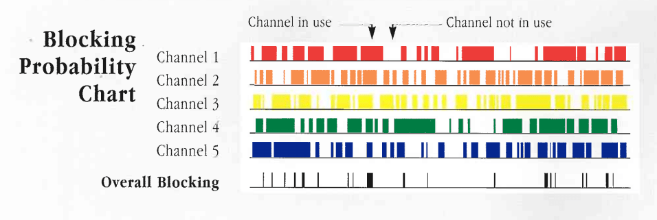 The Blocking Probability Chart represents traffic on a five channel trunked system. The channels represented are approximately fifty percent loaded, meaning the channels are occupied by a radio signal 50% of the time. The colored area represents “in use” repeater time, i.e. when blocking would occur. If the channels were not trunked such that only one channel was available to a user, as in the case of a conventional radio repeater, the user would have only a fifty percent chance of obtaining the use of a channel at any arbitrary instant in time. However, if the user is permitted to select a free channel, the probability of being denied access or getting blocked at any instant is greatly reduced. Compare line six to any of the other five channels. Line six represents the time when there is no channel availability when looking at all five channels together rather than one channel at a time.

Conventional radio is like the old days when you went into a bank and there were 8 tellers with individual lines. You would get into a line and wait to see the teller. Sometimes, there was no one in line, so you went direct to the teller window. Other times, you had 5 people in each line, but it always seemed like the other lines moved significantly faster than the line that you selected. Sometimes the line moved quickly, sometimes it seemed to take forever.
With trunked radio, there is only one line in the bank for the 8 tellers and you go to the first available teller, which keeps you from selecting the only line that does not move. Trunking radio has taken the access to a radio channel from the old teller line to the new line that moves faster and reduces wait time.
Another way of looking at trunking is the difference between having a home phone with several extensions and an office where everyone has access to the first available phone line. At home, you can pick up the phone and dial a number any time you want except when someone else is already using the phone, in which case you must wait until the current phone call is finished. At the office, when you press 9 to get an outside phone line, the system gives you the first available phone line or you select one of the vacant phone lines on the phone. If all the phone lines are in use, you will receive some notification that you have to wait to make a call outside the office.
Interested in trunked radio airtime service? Airtime Services
Interested in clear & crisp expanded digital network coverage? Diga-Talk Network
Interested in renting radios instead of a purchase? Radio Rentals
Interested in an equipment purchase? Products
WARNING: Most of this presentation from this point is very technical and intended for people who want a detailed understanding of how LTR works. If you do not want the technical details, skip down to near the bottom to where it is indicated to RESUME HERE.
LTR Trunking Architecture
LTR uses a system of “home channels” in the repeater system. (Any channel in the system can be a home channel, but it is recommended that at least one channel in the system not have any users assigned to it as a home channel so that it becomes spare parts in something breaks and there are no spare parts available.) Each radio fleet is assigned to monitor a channel which makes that channel the ‘home channel” for that group of radios. Any time you attempt to use the system, the radio will either transmit on the home channel (if it was not in use) or it would switch to another channel that was vacant and transmit on that channel. The radio attempting to talk would know whether or not the channel was in use and where to find an unused channel because the repeater would transmit data simultaneously with the voice (but not heard out of the radio speaker) that tells all radios listening that this channel is in use and where to find an unused channel. If the home channel was available, then the radio would transmit a request to use the channel, receive an acknowledgement that the channel was free and available for that fleet, then start transmitting the voice. If the home channel was busy when an attempt is made to talk, the radio would immediately switch channels, then transmit on the channel that was reported as being free for use requesting the use of that channel, receive an acknowledgement that the channel was free and available for that fleet, then start transmitting the voice. This process would take approximately 0.3 seconds regardless if the radio transmitted on the home channel or another channel which we call a “trunk-off” channel.
| Sync | Area | GOTO | Home Channel | ID Code | Free Repeater | Checksum |
| 8 Bits | 1 Bit | 5 Bits | 5 Bits | 8 Bits | 5 Bits | 8 Bits |
| Valid Range of |
|
|
|
|
|
|
| Standard Sync | 0 or 1 | 1-20, 31 | 1-20 | 1-250 | 1-20, 31 | Calculated as |
To make the system work, the repeater had to transmit data simultaneously with the voice which we call the LTR data. The repeater would transmit LTR data continuously whenever the repeater was transmitting. It repeats the data continuously so that any radio knows what it needs to know all the time. This allows for radios that are just turned on or coming into range from a dead zone to learn what is happening within a second and join a conversation in progress.
When you look at the data above, there are several parts of the data word. They are:
| 1 | Sync Bits | 8 Bits | Std sync pattern |
| 2 | Area Bit | 1 Bit | 0 or 1 |
| 3 | GOTO Channel | 5 Bits | 1-20 |
| 4 | Home Channel | 5 Bits | 1-20 |
| 5 | ID Code | 8 Bits | 1-250 |
| 6 | Free Channel | 5 Bits | 1-20, 31 |
| 7 | Checksum | 8 Bits | As required |
The following is an explanation of the parts of the data word:
- The sync bits provides the decoder a method to find the start of the data word so that the encoder and decoder are synchronized.
- The area bit (Area) is like a master code for the entire system which can be either set to 0 or set to 1. All radios and all repeaters are programmed the same that are part of the same system. If there are two LTR systems on the same set of frequencies, then one should be programmed for area 0 and the other for area 1. This prevents users from the opposing systems from hearing each other and eliminates the system owners from both systems having to coordinate code assignments with each other so that they are not duplicated, causing users to hear each other.
- The GOTO channel (GOTO) part of the data word tells all radios where to find an unused channel while the home channel is in use.
- The Home Channel (HC) part of the data word addresses a specific fleet of radios when paired with the ID Code which is the next part of the data word. However, the Home Channel is used by itself for other reasons that will be discussed later.
- The ID Code (ID) is the unique identifier along with the home channel which identifies a fleet of radios. As an example, home channel 1 can have up to 250 fleets of radios “homed” on channel 1. However, home channel 1 with ID code 1 is not the same fleet of radios as home channel 1 with ID code 2 or home channel 3 with ID code 1. The Home Channel / ID Code combination will together identify a unique fleet of radios.
- The Free Channel (Free) identifies where any radio can find an unused channel for making a radio transmission. The free channel is constantly changing so that each channel in the system gets used about the same amount as another channel.
- The Checksum is calculated by the sending radio and is inserted into the data word. The receiving radio will decode the data and calculate the checksum. If the checksum calculated by the receiving radio and the checksum inserted into the data word by the sending radio match, then the data was correctly decoded and the radio assumes that the data is valid. If the two do not match, then the radio assumes that the data was incorrectly decoded and the data word is ignored.
Let’s assume that the LTR system is programmed with area 0 and that it is the only LTR system on the frequencies. Let’s further assume that we have a 5-channel system and that we have assigned the over the air channel numbers as follows:
| Chan No. | Over The Air Channel Number | Frequency |
| 1 | 02 | 851.0000MHz |
| 2 | 06 | 852.0000MHz |
| 3 | 10 | 853.0000MHz |
| 4 | 14 | 854.0000MHz |
| 5 | 18 | 855.0000MHz |
All radios on the system are programmed with a frequency table that indicates that channel 02 is 851.0000MHz, channel 06 is 852.0000MHz, channel 10 is 853.0000MHz, channel 14 is 854.0000MHz and channel 18 is 855.0000MHz. All frequency data that is sent over the air is strictly the channel number. The radio must look up the frequency in the frequency table to determine the actual frequency in use.
When a subscriber with a portable or mobile radio attempts to access the system that is programmed to Home Channel 02 and ID Code 012, they will press the Push-To-Talk (PTT) button on the microphone (we will assume a mobile radio for the rest of this discussion), the radio will always attempt use the home channel if it is not in use. The radio sends a request to use the home channel because the home channel is not in use. The request sent by the mobile looks like the following:
| Sync | Area 0 | GOTO 02 | HC 02 | ID 012 | Not Used | Checksum |
This essentially means that a radio from fleet HC 02 ID 012 wants to speak to someone within its fleet using channel 02.
The repeater responds with the following message if it is not busy:
| Sync | Area 0 | GOTO 02 | HC 02 | ID 012 | Free 06 | Checksum |
This tells all the mobile radios from the entire fleet to immediately go to channel 02 to hear a conversation for HC 02 ID 012 which is 851.0000MHz. It is also telling all other fleets of radios that there is a available channel which is number 06 which is 852.0000MHz.
If the repeater was busy with another conversation from the fleet of HC 02 ID 135, then the repeater will respond with the following message:
| Sync | Area 0 | GOTO 02 | HC 02 | ID 135 | Free 06 | Checksum |
Your radio will look at the free number 06 and switch to channel number 06 on 852.0000MHz before it requests the use of the channel. The data transmitted by your mobile will look like the following:
| Sync | Area 0 | GOTO 06 | HC 02 | ID 012 | Not Used | Checksum |
The repeater will respond with the following acknowledgement for your radio to access the channel:
| Sync | Area 0 | GOTO 06 | HC 02 | ID 012 | Free 10 | Checksum |
The repeater on channel 06 is saying that HC 02 ID 012 is now using channel 06 and that any other fleet of radios can use channel 10.
However, if you look at the data at the same time on channel 02, you will see the following:
First Data Word:
| Sync | Area 0 | GOTO 02 | HC 02 | ID 012 | Free 10 | Checksum |
This data word tells fleet of HC 02 ID 012 to go to channel 02 on 851.0000MHz for their conversation and channel 10 is free for use by others.
Each data word takes about 150 milliseconds to be sent. Then the repeater sends another data word which would be:
Second Data Word:
| Sync | Area 0 | GOTO 06 | HC 02 | ID 135 | Free 14 | Checksum |
This data word tells fleet of HC 02 ID 135 to go to channel 06 on 852.0000MHz for their conversation and channel 14 is free for use by others.
After the second data word is sent, the repeater continues sending data words, one after another which change each time to support another fleet that has switched to another channel or indicate a different free channel.
Third Data Word:
| Sync | Area 0 | GOTO 02 | HC02 | ID 012 | Free 18 | Checksum |
This data word tells fleet of HC 02 ID 012 to go to channel 02 on 851.0000MHz for their conversation and channel 18 is free for use by others.
Forth Data Word:
| Sync | Area 0 | GOTO 06 | HC 02 | ID 135 | Free 10 | Checksum |
This data word tells fleet of HC 02 ID 135 to go to channel 06 on 852.0000MHz for their conversation and channel 10 is free for use by
others.
Fifth Data Word:
| Sync | Area 0 | GOTO 02 | HC 02 | ID 012 | Free 14 | Checksum |
This data word tells fleet of HC 02 ID 012 to go to channel 02 on 851.0000MHz for their conversation and channel 14 is free for use by
others.
At this point, a radio from the fleet of HC 02 ID 221 attempts to access the repeater system, therefore, a 3rd data word is added to home channel 02 with the following information:
Sixth Data Word:
| Sync | Area 0 | GOTO 14 | HC 02 | ID 221 | Free 18 | Checksum |
This data word tells fleet of HC 02 ID 221 to go to channel 14 on 854.0000MHz for their conversation and channel 18 is free for use by others.
Seventh Data Word:
| Sync | Area 0 | GOTO 02 | HC 02 | ID 012 | Free 10 | Checksum |
This data word tells fleet of HC 02 ID 012 to go to channel 02 on 851.0000MHz for their conversation and channel 10 is free for use by others.
Eighth Data Word:
| Sync | Area 0 | GOTO 06 | HC 02 | ID 135 | Free 18 | Checksum |
This data word tells fleet of HC 02 ID 135 to go to channel 06 on 852.0000MHz for their conversation and channel 18 is free for use by others.
Ninth Data Word:
| Sync | Area 0 | GOTO 14 | HC 02 | ID 221 | Free 10 | Checksum |
This data word tells fleet of HC 02 ID 221 to go to channel 14 on 854.0000MHz for their conversation and channel 10 is free for use by others.
Since there were 3 different fleets from channel 02 using the trunking system, it took 450 milliseconds for the 3 data words to be transmitted to support each of the 3 separate fleets of radios. At this point, the radio from fleet HC 02 ID 012 stops transmitting on channel 02 which makes channel 02 available for use by others.
Tenth Data Word:
| Sync | Area 0 | GOTO 06 | HC02 | ID 135 | Free 18 | Checksum |
This data word tells fleet of HC 02 ID 135 to go to channel 06 on 852.0000MHz for their conversation and channel 18 is free for use by others. The home channel 02 keeps transmitting to support the two conversations that have switched to other channels.
Eleventh Data Word:
| Sync | Area 0 | GOTO 14 | HC 02 | ID 221 | Free 02 | Checksum |
This data word tells fleet of HC 02 ID 221 to go to channel 14 on 854.0000MHz for their conversation and channel 02 is free for use by others. The home channel must keep transmitting to support the conversations of the other two fleets.
Before the next data word is sent, a fleet from channel 14 attempts to use the radio, but their channel is occupied by fleet HC 02 ID 221 who has previously switched to that channel. Therefore, the radios homed on channel 14 are getting messages that indicate a free channel 02, then free channel 10, then free channel 18. When the user presses the PTT button on the radio, the last free channel decoded was channel 02, therefore the radio switches to channel 02 and gets the following data message on channel 02 and the same message is also sent on channel 14, the home repeater for fleet HC 14 ID 097 to notify all other radios in the same fleet that their conversation is on channel 02:
Twelfth Data Word:
| Sync | Area 0 | GOTO 02 | HC 14 | ID097 | Free 10 | Checksum |
This data word tells fleet of HC 14 ID 097 to go to channel 02 on 851.0000MHz for their conversation and channel 10 is free for use by any other fleet.
Thirteenth Data Word:
| Sync | Area 0 | GOTO 06 | HC 02 | ID 135 | Free 18 | Checksum |
This data word tells fleet of HC 02 ID 135 to go to channel 06 on 852.0000MHz for their conversation and channel 18 is free for use by
others.
Fourteenth Data Word:
| Sync | Area 0 | GOTO 14 | HC 02 | ID 221 | Free 10 | Checksum |
This data word tells fleet of HC 02 ID 221 to go to channel 14 on 854.0000MHz for their conversation and channel 10 is free for use by others.
After a short time, the fleets that have switched to other channels will stop transmitting and the channel will become idle. Eventually another subscriber that is programmed to use home channel 02 will start transmitting. Therefore, a new sequence will start and eventually see the following:
First Data Word:
| Sync | Area 0 | GOTO 02 | HC 02 | ID 075 | Free 14 | Checksum |
This data word tells fleet of HC 02 ID 075 to go to channel 02 on 851.0000MHz for their conversation and channel 14 is free for use by others.
Second Data Word:
| Sync | Area 0 | GOTO 02 | HC 02 | ID 075 | Free 06 | Checksum |
This data word tells fleet of HC 02 ID 075 to go to channel 02 on 851.0000MHz for their conversation and channel 06 is free for use by others. The repeater skipped channel 18 because there was a conversation occurring on channel 18, channel 02 was in use by HC 02 ID 075, so the next free channel was channel 06.
If all repeaters are in use, the free channel number will change to 31 to indicate no free channels.
This type of operation happens continuously on the various channels of the trunking system throughout the day and night. Each event is triggered by someone pressing the PTT button to attempt the start of a conversation or to respond to a call on the radio.
The selection of the channel numbers which can be channel 1 through channel 20 was evenly spaced instead of selecting channels 1-5. The reason for this is to even out the loading between channels. Aside from being channel numbers, it also refers to time slots. There are 20 time slots for repeaters and one more time slot for the system use. By spacing the channels 2-6-10-14-18, the amount of time that each repeater is represented as a free repeater is an equal amount of time. This distributes the loading more evenly over the system so that you do not have channels that talk all the time and other channels that almost never talk so that you do not get excessive wear and tear on the power amplifiers for some channels while other channels never talk.
The last issue is the 21st time slot which is used by the system to invalidate subscribers that have been shut off for some reason. (This time slot is in the repeater system data bus that connects all the repeaters together so that they all know what each other are doing at any given time.) Usually, fleets are shut off for failure to pay their bill, but they are also shut off for other reasons which include stolen equipment, malicious interference or fleets that have discontinued service. When a fleet of radios appear in time slot 21, the repeater changes the GOTO data to 31 instead of a valid channel number to force the radio to be unable to transmit.
Exclusive Channels Required
LTR systems require all exclusive channels to operate in the most efficient manner possible. However, in most cases, it is not possible to have 100% exclusive channels. All the channels that are assigned to be home channels must be exclusive channels because the mobile radios transmit without monitoring the channel. Non home channels can be shared channels provided that the system is programmed to monitor the channel and lock out the channel when it is in use by a co-channel user. This makes the channel unavailable at times due to the co-channel traffic and reduces the overall system capacity which can be made up by adding another shared channel. Also, even though the system will not assign a shared channel when the shared channel is in use by another co-channel user, nothing stops the co-channel user from transmitting after the channel is assigned by the LTR system which will interfere with the LTR system user.
For a more complete discussion of benefit of exclusive channels, please see the article, “Exclusive vs Shared Channels”.
Resume Reading Here if you skipped the technical
discussion:
LTR trunking is a simple, yet straightforward method of assigning unused channels for use by any radio fleet that wants to initiate a conversation. With the use of a data decoder, it is easy to determine over the air which customer is on what channel at what time. Each subscriber has a “virtual” private channel while they are transmitting, because no other subscriber can switch to the same channel as another subscriber at the same time.
Advanced Features
There are many advanced features in LTR beyond the basic features described above that go beyond the features that are available in conventional radios. These include the ability to have multiple fleets for a given customer. An example of a cement company that has 3 different groups of radios; cement mixers, sand and gravel trucks and field mechanics that take care of mechanical problems with the trucks in the field. The cement mixers are on one HC/ID code, the sand and gravel trucks are on another HC/ID code and the mechanics are on a 3rd HC/ID code. Radios can be programmed to listen to only one of the fleets, any combination of the fleets, all the fleets, scan the fleets, switch manually between fleets or be able to call all the fleets at once. There are ways to make it so that mobiles cannot talk to mobiles, they can only talk to the base station at the office. Each of these features are available in almost any model radio made today. One can switch their radio to fleets from other companies (with permission from the other company) to coordinate jobs with other companies. Emergency fleets (talk groups) can be programmed that override other talk groups. The system owner can program all the subscriber radios on the system to hear a broadcast from the system owner.
Interested in trunked radio airtime service? LTR Coverage
Interested in clear & crisp expanded digital network coverage? The Diga-Talk Network
In summary, there is a lot of versatility built into the system to do whatever is needed by a subscriber. However, the limitation of LTR is that it is an analog technology, therefore, it does not have the advanced features that are built into digital radio technology. The main feature that is lacking in LTR is that each site is stand alone and not connected to other LTR sites into a network. This means that a subscriber must manually switch tower sites whenever the subscriber runs out of coverage from the site that was in use. It also means that the person to whom you are speaking must also switch tower sites to the same tower site that you are switch to yourself. If you switch to a different tower site than the person with whom you were speaking, your conversation terminates immediately because you cannot speak to anyone who is not using the same tower site as yourself. This causes problems when you need coverage in an area that cannot be reached by the office or anyone else in your fleet that needs to speak with you. For subscribers who can get all the coverage that they need from one tower site, this is not any problem, but most fleets want more coverage than can be achieved by a single tower site. For those subscribers, it is best to consider a digital radio system.